Infiniti Q45 (FY33). Manual - part 97
SBR670DB
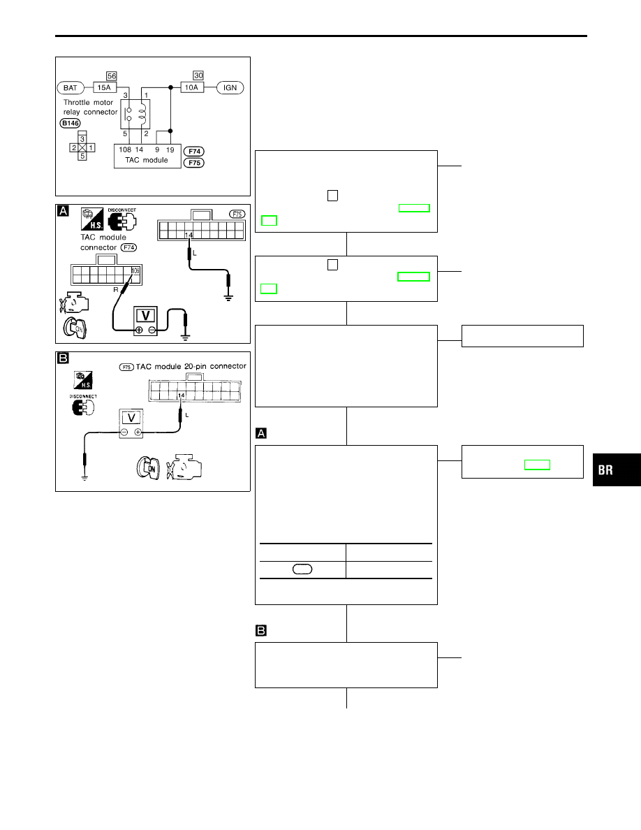
Diagnostic Procedure 18 (THROTTLE MOTOR
RLY [SHORT] (-a)/THROTTLE MOTOR RLY
[OPEN] (-b): Throttle motor relay circuit for
open circuit and short circuit)
Code No. 23 and 24 of TAC module
SBR671D
SBR553CA
THROTTLE MOTOR RELAY POWER
SUPPLY CHECK
----------------------------------------------------------------------------------------------------------------------------------------------------------------------------------------------------------------------------------------------------------------------------------------------------------------
Check 15A fuse
56
. For fuse layout, refer
to POWER SUPPLY ROUTING in EL sec-
tion.
OK
E
NG
q
A
(Go to next page.)
Check 10A fuse
30
. For fuse layout, refer
to POWER SUPPLY ROUTING in EL sec-
tion.
OK
E
NG
q
B
(Skip page.)
1. Disconnect TAC module connector.
Check terminals for damage or loose
connection. Then reconnect connectors.
2. Carry out self-diagnosis again.
Do SLIP indicator and TCS OFF indi-
cator activate again?
Yes
E
No
Inspection end
THROTTLE MOTOR RELAY CIRCUIT
----------------------------------------------------------------------------------------------------------------------------------------------------------------------------------------------------------------------------------------------------------------------------------------------------------------
I
Disconnect connectors from TAC mod-
ule.
I
Turn ignition switch ON.
I
Check voltage between the following
terminals by grounding terminal
q
14
.
Battery voltage should exist.
NG
E
OK
Preliminary check (Basic
inspection 3), BR-48
Check voltage between terminal
q
14
for
TAC module connector and ground.
Battery voltage should exist.
NG
E
OK
q
D
(Skip page.)
q
C
TAC module
Motor
108
Ground
GI
MA
EM
LC
EC
FE
AT
PD
FA
RA
ST
RS
BT
HA
EL
IDX
TROUBLE DIAGNOSES FOR SELF-DIAGNOSTIC ITEMS
H
H
H
H
H
BR-105