Infiniti Q45 (FY33). Manual - part 94
SBR371E
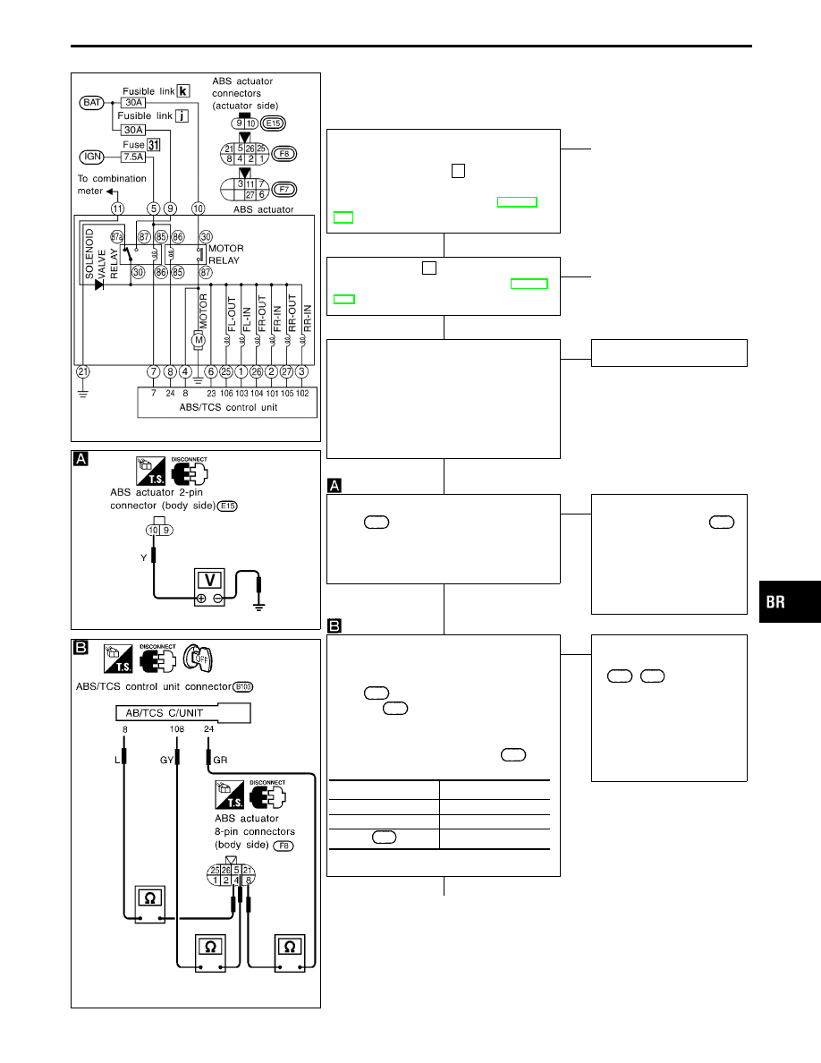
Diagnostic Procedure 10 (Motor relay or motor)
Code No. 61 of ABS/TCS control unit
SBR379E
SBR380E
MOTOR POWER SUPPLY CIRCUIT
----------------------------------------------------------------------------------------------------------------------------------------------------------------------------------------------------------------------------------------------------------------------------------------------------------------
Check 30A fusible link k
for ABS actua-
tor. For fusible link layout, refer to
POWER SUPPLY ROUTING in EL sec-
tion.
OK
E
NG
q
B
(Skip page.)
Check 7.5A fuse
31
. For fuse layout, refer
to POWER SUPPLY ROUTING in EL sec-
tion.
OK
E
NG
q
C
(See next page.)
1. Disconnect connectors from ABS/TCS
control unit and ABS actuator. Check
terminals for damage or loose connec-
tion. Then reconnect connectors.
2. Carry out self-diagnosis again.
Do ABS warning lamp and TCS OFF
indicator activate again?
Yes
E
No
Inspection end
1. Disconnect ABS actuator 2-pin connec-
tor
E15
.
2. Check voltage between connector
(body side) terminal
q
10
and ground.
Battery voltage should exist.
OK
E
NG
Check the following.
I
Harness connector
E15
I
Harness for open or
short between ABS
actuator and fuse
If NG, repair harness or
connectors.
CIRCUIT CHECK
----------------------------------------------------------------------------------------------------------------------------------------------------------------------------------------------------------------------------------------------------------------------------------------------------------------
1. Disconnect ABS actuator 8-pin connec-
tor
F8
and ABS/TCS control unit con-
nector
B103
.
2. Check continuity between ABS/TCS
control unit connector terminals and
ABS actuator 8-pin connector
F8
(body side) terminals.
Continuity should exist.
OK
E
NG
Check the following.
I
Harness connectors
F8
,
B103
I
Harness for open or short
between ABS actuator
(body side) and ABS/TCS
control unit
If NG, repair harness or
connectors.
q
A
(Go to next page.)
Control unit
ABS relay unit
q
24
q
8
q
8
q
4
108
q
5
GI
MA
EM
LC
EC
FE
AT
PD
FA
RA
ST
RS
BT
HA
EL
IDX
TROUBLE DIAGNOSES FOR SELF-DIAGNOSTIC ITEMS
H
H
H
H
H
BR-93