Infiniti Q45 (FY33). Manual - part 87
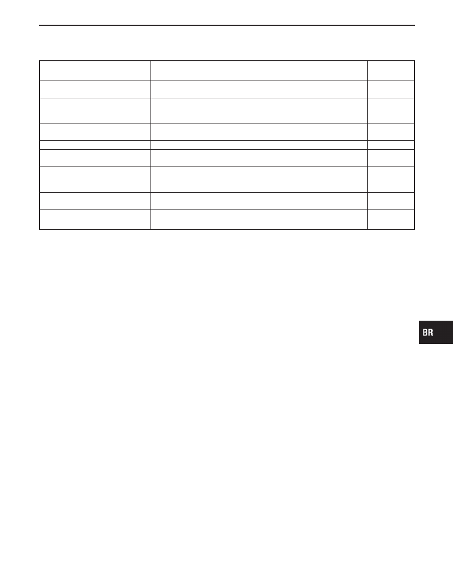
Diagnostic item
Diagnostic item is detected when ...
Diagnostic
procedure
LAN SIGNAL 1
I
ECM judges that communication signal between ABS/TCS control unit
and ECM is abnormal.
4
LAN SIGNAL 2
I
On the Local Area Network (LAN) between ABS/TCS control unit and
ECM, ECM does not transmit the LAN start signal to ABS/TCS control
unit.
5
LAN SIGNAL 3
I
The communication start signal output is not terminated and the ordinary
signals are not entered to ABS/TCS control unit.
—
ENGINE SPEED SIG
I
Engine speed signal from ECM is not entered.
3
ENGINE SYSTEM
I
Based on the signal from ECM, the ABS/TCS control unit judges that the
engine control system is malfunctioning.
1
TAC COMM
I
The communication signal between ABS/TCS control unit and Throttle
Actuator Control Module (TAC Module) is abnormal or this communica-
tion line is open or shorted.
2
LAN CIRCUIT 1
I
The communication line between ABS/TCS control unit and ECM is open
or shorted.
6
LAN CIRCUIT 2
I
An instantaneous signal interruption occurs repeatedly on the communi-
cation line between ABS/TCS control unit and ECM.
6
I
If the ABS warning lamp activates and Self-diagnosis could not detect any malfunctions, perform “Diag-
nostic Procedure 3”.
GI
MA
EM
LC
EC
FE
AT
PD
FA
RA
ST
RS
BT
HA
EL
IDX
TROUBLE DIAGNOSES
CONSULT-II Inspection Procedure for ABS/TCS
Control Unit (Cont’d)
BR-65