Infiniti Q45 (FY33). Manual - part 78
SBR048C
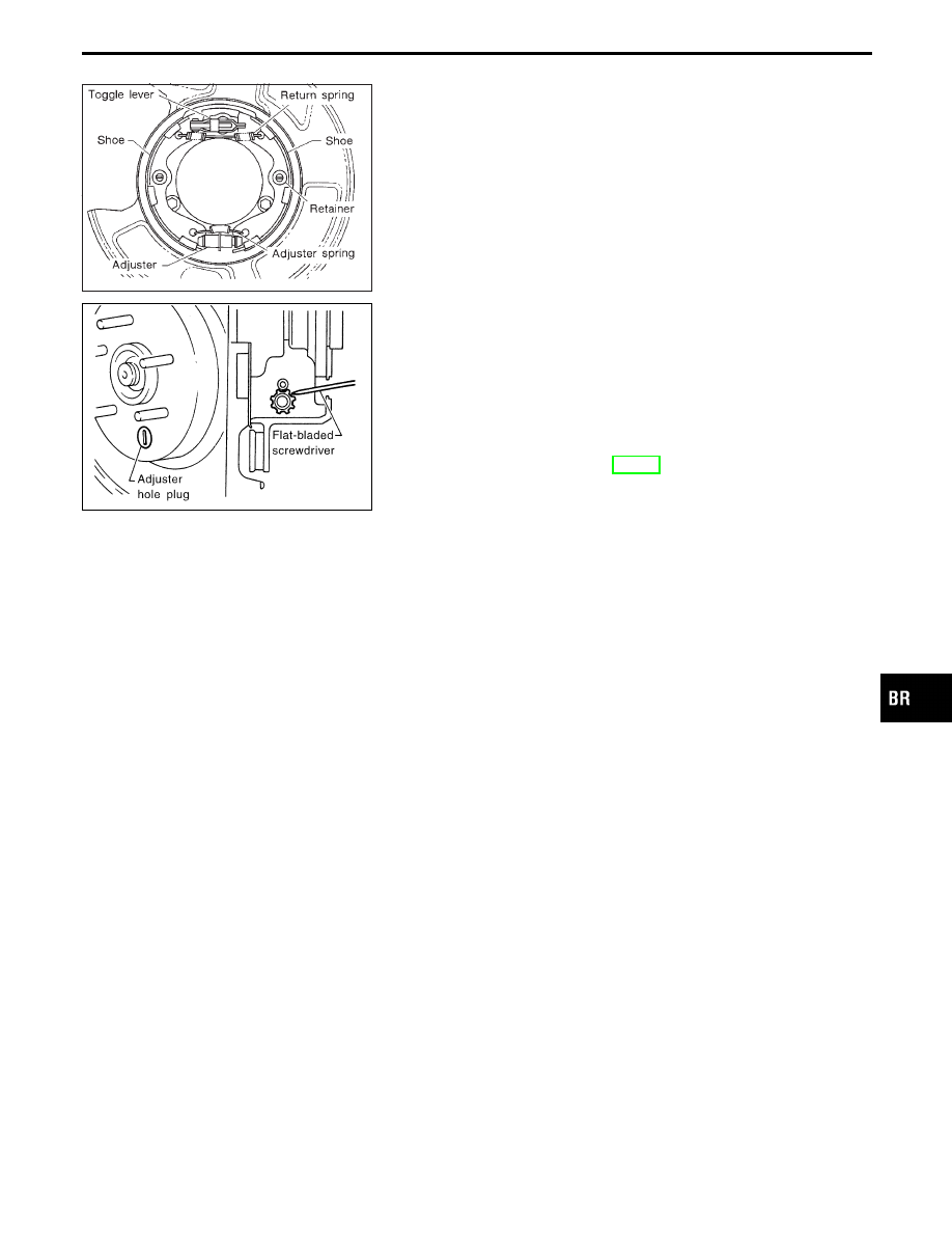
6.
Check all parts are installed properly.
Pay attention to direction of adjuster and toggle lever.
7.
Install drum.
8.
Install rear disc brake assembly.
SBR097CA
Shoe Clearance Adjustment
1.
Remove adjuster hole plug, and turn down adjuster wheel with
a flat-bladed screwdriver until brake is locked.
Make sure that parking control lever is released completely.
2.
Return adjuster wheel 5 to 6 latches.
3.
Install adjuster hole plug, and make sure that there is no drag
between shoes and brake drum when rotating disc rotor.
4.
Adjust parking brake cable. Refer to “Adjustment” in “PARK-
ING BRAKE CONTROL”, BR-31.
Breaking in Drum and Lining
When a new rotor/parking brake shoe is installed, or when braking
performance is poor, perform the following break-in procedure.
1.
Drive the unloaded vehicle on a safe, level and dry road.
2.
Depress parking brake pedal with a force of 147 N (15 kg, 33
lb).
3.
While depressing the pedal, continue to drive the vehicle for-
ward 100 m (328 ft) at approximately 35 km/h (22 MPH).
4.
Cool down parking brake for approx. five minutes.
5.
After releasing the pedal, drive the vehicle under the normal
conditions for two minutes to cool down the parking drum
brake.
6.
Repeat steps 1 through 5 three times and then repeat only step
5 one more time.
GI
MA
EM
LC
EC
FE
AT
PD
FA
RA
ST
RS
BT
HA
EL
IDX
REAR DISC BRAKE — Parking Drum Brake
Installation (Cont’d)
BR-29