Infiniti Q45 (FY33). Manual - part 65


  Index      Infiniti     Infiniti Q45 (FY33) - service repair manual 2001 year


Search            copyright infringement  


Content   ..  63  64  65  66   ..


Infiniti Q45 (FY33). Manual - part 65


SAT229H

ASSEMBLY

1.

Install parking actuator support onto rear extension.
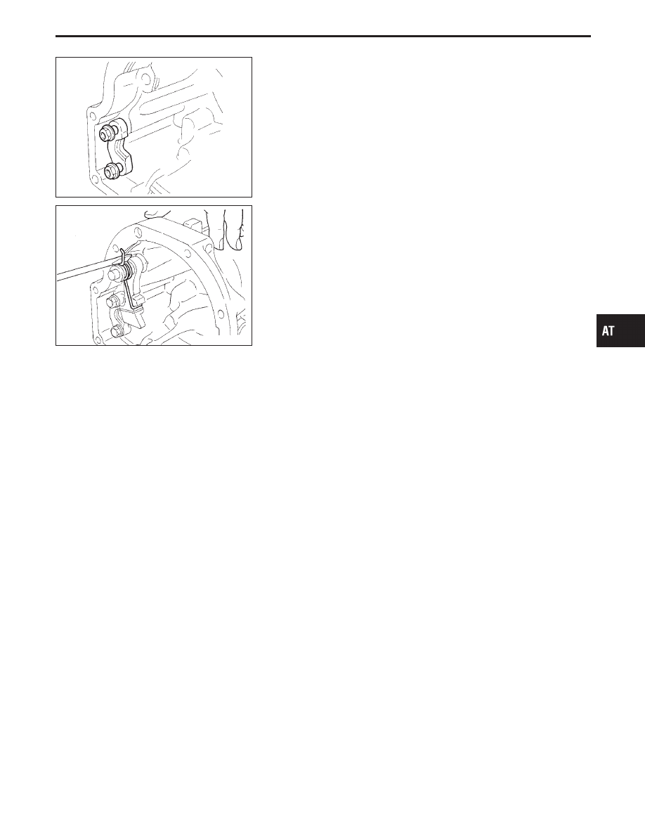
2.

Insert parking pawl shaft into rear extension.

3.

Install return spring, pawl spacer and parking pawl onto park-
ing pawl shaft.

SAT226H

4.

Bend return spring upward and install it onto rear extension.

GI

MA

EM

LC

EC

FE

PD

FA

RA

BR

ST

RS

BT

HA

EL

IDX

REPAIR FOR COMPONENT PARTS

Parking Pawl Components (Cont’d)

AT-257

SAT931A

Assembly (1)

1.

Install manual shaft components.

a.

Install oil seal onto manual shaft.

I

Apply ATF to oil seal.

I

Wrap threads of manual shaft with masking tape.

b.

Insert manual shaft and oil seal as a unit into transmission
case.

c.

Remove masking tape.

SAT932A

d.

Push oil seal evenly and install it onto transmission case.

SAT933A

e.

Align groove in shaft with drive pin hole, then drive pin into
position as shown in figure at left.

SAT934A

f.

Install detent spring and spacer.

SAT935A

g.

While pushing detent spring down, install manual plate onto
manual shaft.

ASSEMBLY

AT-258

SAT936A

h.

Install lock nuts onto manual shaft.

SAT937AA

2.

Install accumulator piston.

a.

Install O-rings onto accumulator piston.

I

Apply ATF to O-rings.

Accumulator piston O-rings:

Refer to SDS, AT-278.

SAT938A

b.

Install return spring for accumulator

q

A

onto transmission case.

Free length of return spring:

Refer to SDS, AT-277.

SAT939AA

c.

Install accumulator pistons

q

A

,

q

B

,

q

C

and

q

D

.

I

Apply ATF to transmission case.

SAT717H

3.

Install band servo piston.

a.

Install return spring onto servo piston.

GI

MA

EM

LC

EC

FE

PD

FA

RA

BR

ST

RS

BT

HA

EL

IDX

ASSEMBLY

Assembly (1) (Cont’d)

AT-259

SAT942A

b.

Install band servo piston onto transmission case.

I

Apply ATF to O-ring of band servo piston and transmis-
sion case.

c.

Install gasket for band servo onto transmission case.

SAT940A

d.

Install band servo retainer onto transmission case.

SAT943A

4.

Install rear side clutch and gear components.

a.

Place transmission case in vertical position.

SAT944A

b.

Slightly lift forward clutch drum assembly and slowly rotate it
clockwise until its hub passes fully over the clutch inner race
inside transmission case.

SAT945A

c.

Check to be sure that rotation direction of forward clutch
assembly is correct.

ASSEMBLY

Assembly (1) (Cont’d)

AT-260


Content   ..  63  64  65  66   ..