Infiniti Q45 (FY33). Manual - part 56
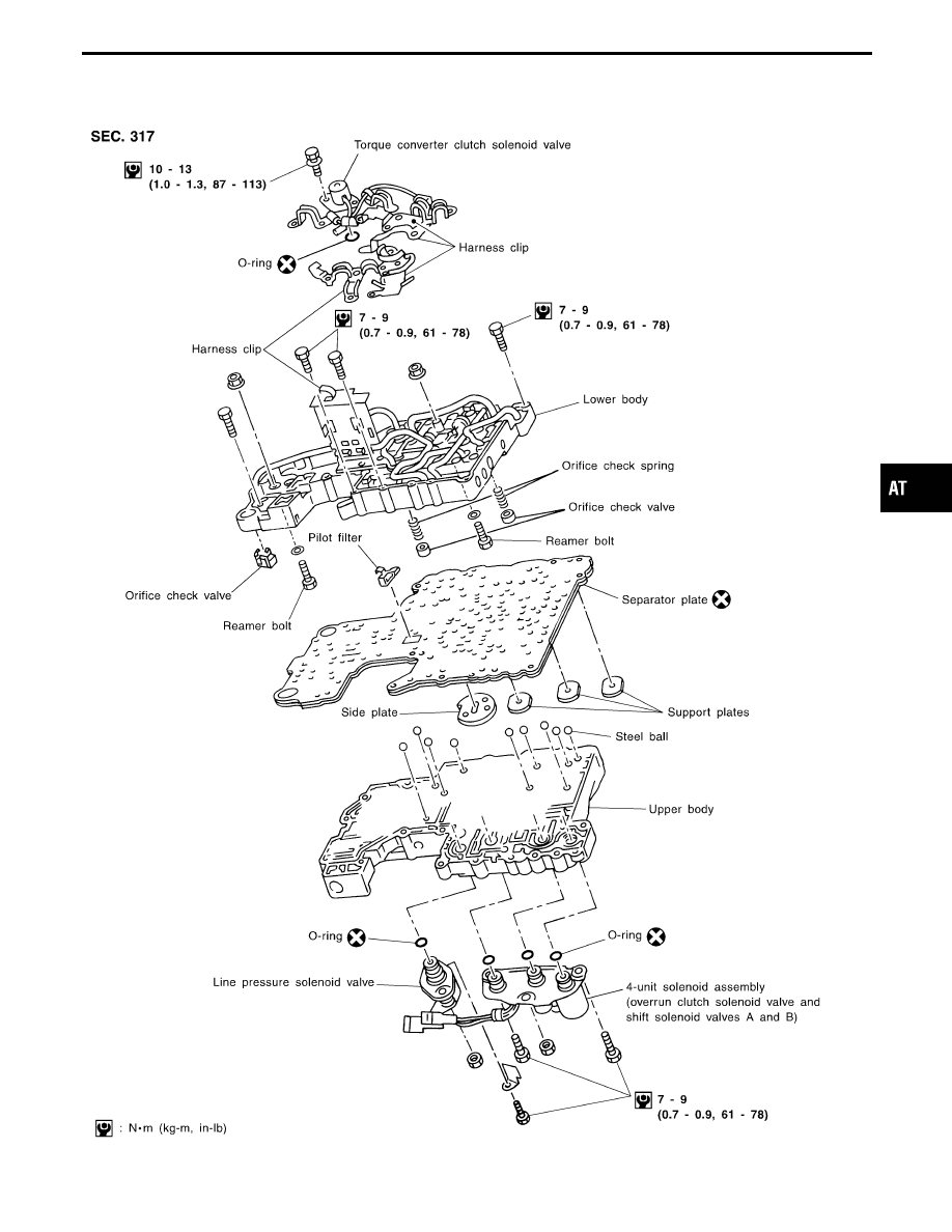
Control Valve Assembly
SAT742J
GI
MA
EM
LC
EC
FE
PD
FA
RA
BR
ST
RS
BT
HA
EL
IDX
REPAIR FOR COMPONENT PARTS
AT-221
|
|
|
Control Valve Assembly SAT742J GI MA EM LC EC FE PD FA RA BR ST RS BT HA EL IDX REPAIR FOR COMPONENT PARTS AT-221 |