Infiniti Q45 (FY33). Manual - part 49
SAT605I
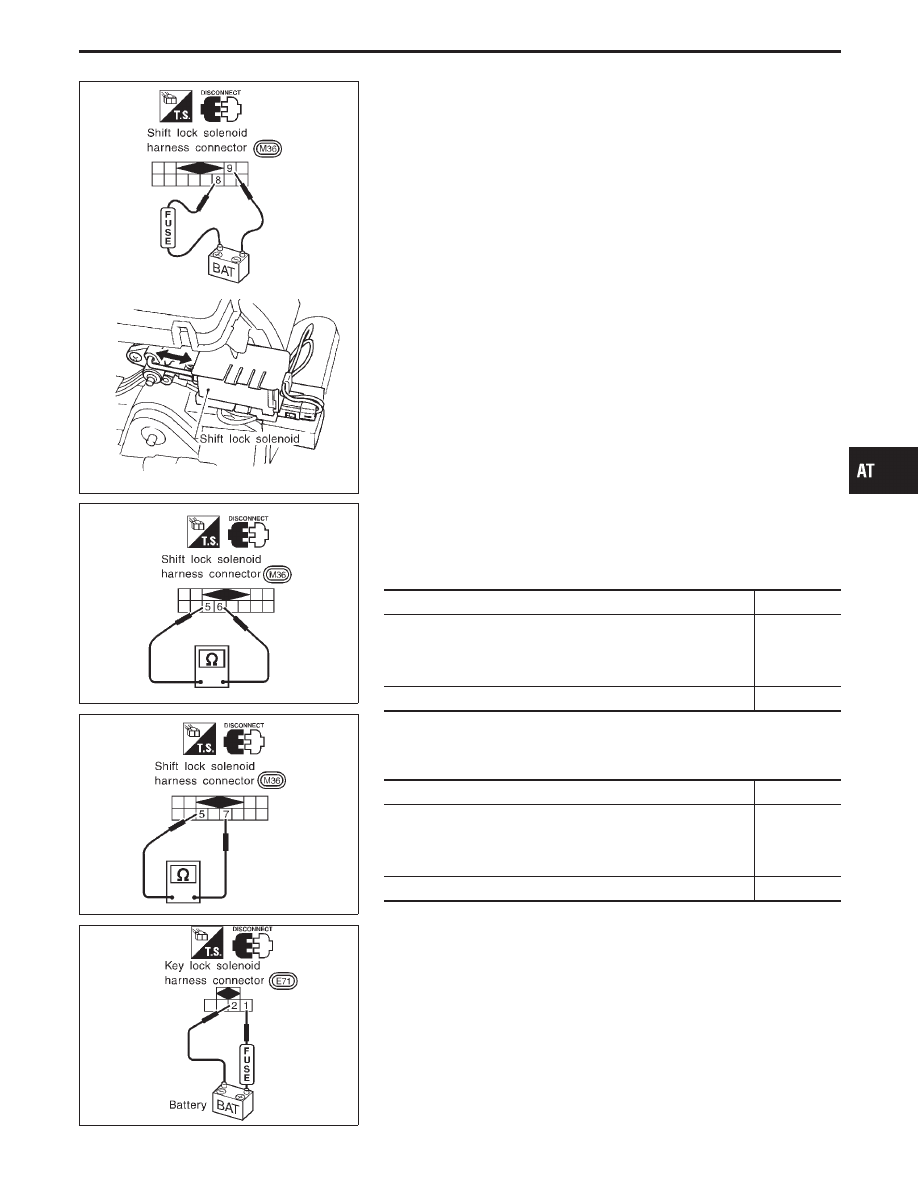
Component Check
SHIFT LOCK SOLENOID
I
Check operation by applying battery voltage to shift lock sole-
noid harness connector.
SAT606I
SAT607I
DETENTION SWITCH
Shift
I
Check continuity between terminals
q
5
and
q
6
of shift lock
solenoid harness connector.
Condition
Continuity
I
When selector lever is set in “P” position, and selector lever
button pushed.
I
When selector lever is set in any position except “P”, and
selector lever button released.
Yes
Except the above
No
Key
I
Check continuity between terminals
q
5
and
q
7
of shift lock
solenoid harness connector.
Condition
Continuity
I
When selector lever is set in “P” position, and selector lever
button pushed.
I
When selector lever is set in any position except “P”, and
selector lever button released.
Yes
Except the above
No
SAT608I
KEY LOCK SOLENOID
I
Check operation by applying battery voltage to key lock sole-
noid harness connector.
Operating sound must be emitted.
GI
MA
EM
LC
EC
FE
PD
FA
RA
BR
ST
RS
BT
HA
EL
IDX
TROUBLE DIAGNOSES — A/T Shift Lock System
AT-193