Infiniti Q45 (FY33). Manual - part 39
SAT738J
SAT943IA
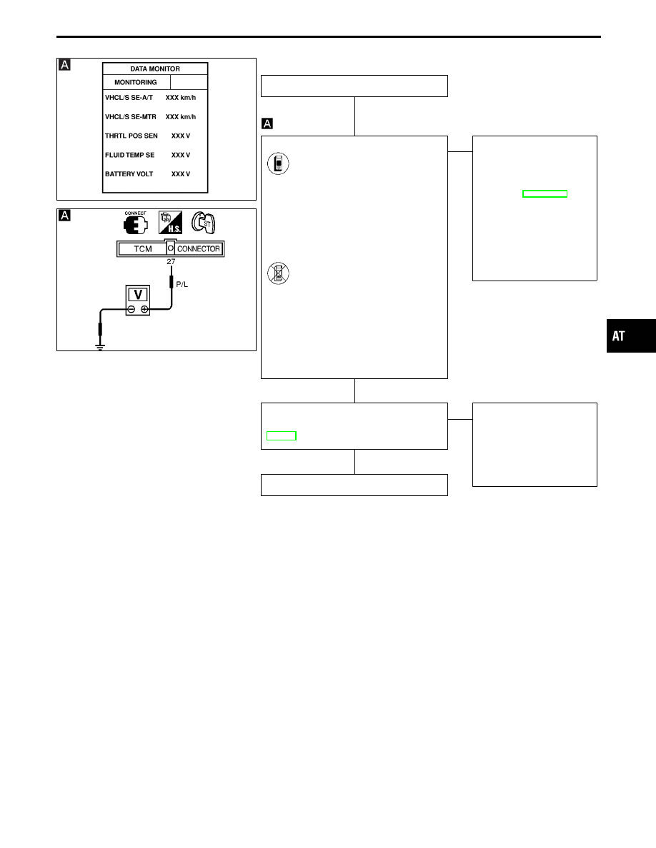
DIAGNOSTIC PROCEDURE
INSPECTION START
CHECK INPUT SIGNAL.
1. Start engine.
2. Select “TCM INPUT SIGNALS”
in “DATA MONITOR” mode for
“A/T” with CONSULT-II.
3. Read out the value of “VHCL/S
SE
⋅
MTR” while driving.
Check the value changes
according to driving speed.
-------------------------------------------------------------------------------------------------------------------------------------- OR --------------------------------------------------------------------------------------------------------------------------------------
1. Start engine.
2. Check voltage between TCM
terminal
q
27
and ground while
driving at 2 to 3 km/h (1 to 2
MPH) for 1 m (3 ft) or more.
Voltage:
Voltage varies between less
than 1V and more than
4.5V.
OK
E
NG
Check the following items:
I
Vehicle speed sensor
and ground circuit for
vehicle speed sensor
Refer to EL section
(“METERS AND
GAUGES”).
I
Harness for short or
open between TCM and
vehicle speed sensor
(Main harness)
Perform DIAGNOSTIC TROUBLE CODE
(DTC) CONFIRMATION PROCEDURE,
AT-152.
OK
E
NG
1. Perform TCM input/
output signal inspection.
2. If NG, recheck TCM pin
terminals for damage or
loose connection with
harness connector.
INSPECTION END
GI
MA
EM
LC
EC
FE
PD
FA
RA
BR
ST
RS
BT
HA
EL
IDX
TROUBLE DIAGNOSIS FOR VHCL SPEED SEN
⋅
MTR
Vehicle Speed Sensor
⋅
MTR (Cont’d)
H
H
H
AT-153