Infiniti Q45 (FY33). Manual - part 32
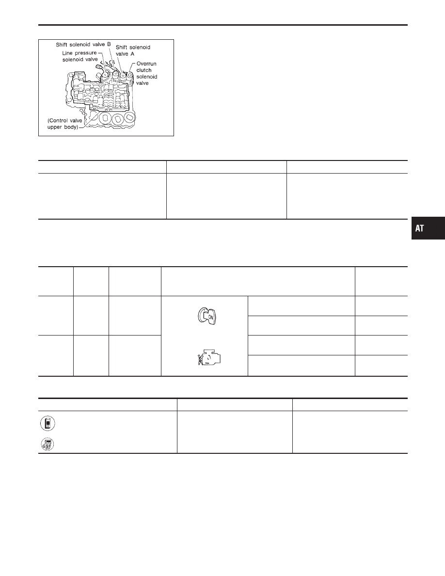
SAT341H
Line Pressure Solenoid Valve
DESCRIPTION
The line pressure solenoid valve regulates the oil pump discharge
pressure to suit the driving condition in response to a signal sent
from the TCM.
The line pressure duty cycle value is not consistent when the
closed throttle position switch is “ON”. To confirm the line
pressure duty cycle at low pressure, the accelerator (throttle)
should be open until the closed throttle position switch is
“OFF”.
CONSULT-II REFERENCE VALUE IN DATA MONITOR MODE
Remarks: Specification data are reference values.
Monitor item
Condition
Specification
Line pressure solenoid valve duty
Small throttle opening
(Low line pressure)
"
Large throttle opening
(High line pressure)
Approximately 29%
"
Approximately 95%
Note: The line pressure duty cycle value is not consistent when the closed throttle position switch is “ON”. To confirm the line
pressure duty cycle at low pressure, the accelerator (throttle) should be open until the closed throttle position switch is
“OFF”.
TCM TERMINALS AND REFERENCE VALUE
Remarks: Specification data are reference values.
Terminal
No.
Wire color
Item
Condition
Judgement
standard
(Approx.)
1
G/R
Line pressure
solenoid valve
When releasing accelerator pedal
after warming up engine.
1.5 - 2.5V
When depressing accelerator pedal
fully after warming up engine.
0V
2
W/B
Line pressure
solenoid valve
(with dropping
resistor)
When releasing accelerator pedal
after warming up engine.
5 - 14V
When depressing accelerator pedal
fully after warming up engine.
0V
ON BOARD DIAGNOSIS LOGIC
Diagnostic trouble code
Malfunction is detected when ...
Check item (Possible cause)
: L/PRESS SOL/CIRC
TCM detects an improper voltage drop
when it tries to operate the solenoid
valve.
I
Harness or connectors
(The solenoid circuit is open or
shorted.)
I
Line pressure solenoid valve
: P0745
GI
MA
EM
LC
EC
FE
PD
FA
RA
BR
ST
RS
BT
HA
EL
IDX
TROUBLE DIAGNOSIS FOR DTC P0745
AT-125