Infiniti Q45 (FY33). Manual - part 30


  Index      Infiniti     Infiniti Q45 (FY33) - service repair manual 2001 year


Search            copyright infringement  


Content   ..  28  29  30  31   ..


Infiniti Q45 (FY33). Manual - part 30


SAT543I

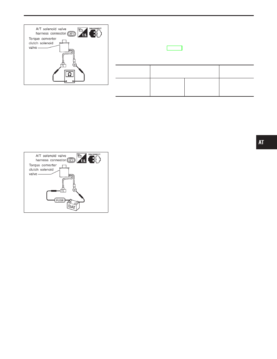
COMPONENT INSPECTION

Torque converter clutch solenoid valve

I

For removal, refer to AT-195.

Resistance check

I

Check resistance between two terminals.

Solenoid valve

Terminal No.

Resistance

(Approx.)

Torque converter
clutch solenoid
valve

q

7

Ground

10 - 20

SAT544I

Operation check

I

Check solenoid valve by listening for its operating sound while
applying battery voltage to the terminal and ground.

GI

MA

EM

LC

EC

FE

PD

FA

RA

BR

ST

RS

BT

HA

EL

IDX

TROUBLE DIAGNOSIS FOR DTC P0740

Torque Converter Clutch Solenoid Valve
(Cont’d)

AT-117

A/T TCC S/V Function (Lock-up)

DESCRIPTION

I

This is an OBD-II self-diagnostic item and not available in TCM self-diagnosis.

I

This malfunction will not be detected while the O/D OFF indicator lamp is indicating another self-diagno-
sis malfunction.

I

This malfunction is detected when the A/T does not shift into fourth gear position or the torque converter
clutch does not lock up as instructed by the TCM. This is not caused by electrical malfunction (circuits open
or shorted) but by mechanical malfunction such as control valve sticking, improper solenoid valve
operation, malfunctioning oil pump or torque converter clutch, etc.

CONSULT-II REFERENCE VALUE IN DATA MONITOR MODE

Remarks: Specification data are reference values.

Monitor item

Condition

Specification

Torque converter clutch solenoid valve duty

Lock-up “OFF”

"

Lock-up “ON”

Approximately 4%

"

Approximately 94%

TCM TERMINALS AND REFERENCE VALUE

Remarks: Specification data are reference values.

Terminal

No.

Wire color

Item

Condition

Judgement

standard

(Approx.)

1

G/R

Line pressure
solenoid valve

When releasing accelerator pedal
after warming up engine.

1.5 - 2.5V

When depressing accelerator pedal
fully after warming up engine.

0V

2

W/B

Line pressure
solenoid valve
(with dropping
resistor)

When releasing accelerator pedal
after warming up engine.

5 - 14V

When depressing accelerator pedal
fully after warming up engine.

0V

5

G/B

Torque converter
clutch solenoid
valve

When A/T performs lock-up.

8 - 15V

When A/T does not perform lock-up.

0V

TROUBLE DIAGNOSIS FOR DTC P0744

AT-118

ON BOARD DIAGNOSTIC LOGIC

This diagnosis monitors actual gear position by checking the torque converter slip ratio calculated by TCM as
follows:
Torque converter slip ratio = A x C/B
A: Output shaft revolution signal from revolution sensor
B: Engine speed signal from ECM
C: Gear ratio determined as gear position which TCM supposes
If the actual gear position is much lower than the position (4th) supposed by TCM, the slip ratio will be much
less than normal. In case the ratio does not reach the specified value, TCM judges this diagnosis malfunction.
This malfunction will be caused when shift solenoid valve B is stuck closed.

Gear position supposed by TCM

1

2

3

4

In case of gear position with no malfunc-
tions

1

2

3

4

In case of gear position with shift solenoid
valve B stuck closed

1

2

2

q

1

q

: P0744 is detected.

Diagnostic trouble code

Malfunction is detected when ...

Check item (Possible cause)

: A/T TCC S/V FNCTN

A/T cannot perform lock-up even if
electrical circuit is good.

I

Torque converter clutch solenoid
valve

I

Line pressure solenoid valve

I

Each clutch

I

Hydraulic control circuit

: P0744

SAT014K

SAT971J

DIAGNOSTIC TROUBLE CODE (DTC) CONFIRMA-
TION PROCEDURE

CAUTION:

Always drive vehicle at a safe speed.
NOTE:
If “DIAGNOSTIC TROUBLE CODE CONFIRMATION PROCE-
DURE” has been previously conducted, always turn ignition
switch “OFF” and wait at least 5 seconds before conducting
the next test.
After the repair, perform the following procedure to confirm the
malfunction is eliminated.

1)

Start engine and select “DATA MONITOR” mode for
“A/T” with CONSULT-II.

2)

Make sure that output voltage of A/T fluid temperature
sensor is within the range below.
FLUID TEMP SEN: 0.4 - 1.5V
If out of range, drive the vehicle to decrease the voltage
(warm up the fluid) or stop engine to increase the volt-
age (cool down the fluid).

3)

Select “TCC S/V FNCTN P0744” of “DTC WORK SUP-
PORT” mode for “A/T” with CONSULT-II and touch
“START”.

GI

MA

EM

LC

EC

FE

PD

FA

RA

BR

ST

RS

BT

HA

EL

IDX

TROUBLE DIAGNOSIS FOR DTC P0744

A/T TCC S/V Function (Lock-up) (Cont’d)

AT-119

SAT021J

4)

Accelerate vehicle to more than 80 km/h (50 MPH) and
maintain the following condition continuously until
“TESTING” has turned to “COMPLETE”. (It will take
approximately 30 seconds after “TESTING” shows.)
THROTTLE POSI: 1.0/8 - 2.0/8 (at all times during
step 4)
Selector lever: D position (OD “ON”)
TCC S/V DUTY: More than 94%
VHCL/S SE

A/T: Constant speed of more than 80

km/h (50 MPH)

I

Check that “GEAR” shows “4”.

I

For shift schedule, refer to SDS, AT-276.

I

If “TESTING” does not appear on CONSULT-II for a
long time, select “SELF-DIAG RESULTS”. In case a
1st trip DTC other than P0744 is shown, refer to
applicable “TROUBLE DIAGNOSIS FOR DTC”.

5)

Make sure that “OK” is displayed. (If “NG” is displayed,
refer to “DIAGNOSTIC PROCEDURE”.)
Refer to “DIAGNOSTIC PROCEDURE”, AT-121.
Refer to shift schedule, AT-276.

------------------------------------------------------------------------------------------------------------------------------------------------------------------------------------------------------------------------------------------------------ OR ------------------------------------------------------------------------------------------------------------------------------------------------------------------------------------------------------------------------------------------------------

Follow the procedure “With CONSULT-II”.

TROUBLE DIAGNOSIS FOR DTC P0744

A/T TCC S/V Function (Lock-up) (Cont’d)

AT-120


Content   ..  28  29  30  31   ..