Infiniti Q45 (FY33). Manual - part 20
SAT010C
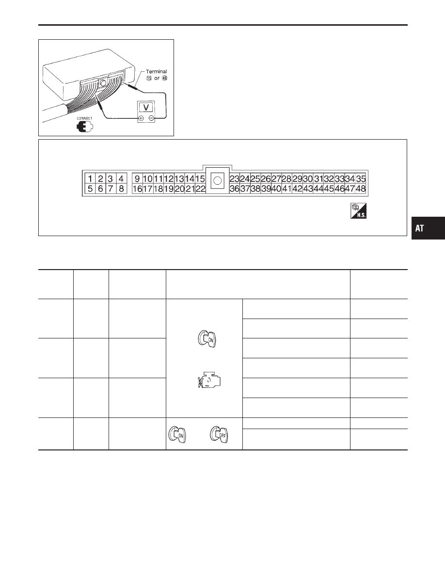
TCM Terminals and Reference Value
PREPARATION
I
Measure voltage between each terminal and terminal
q
15
or
q
48
by following “TCM INSPECTION TABLE”.
TCM HARNESS CONNECTOR TERMINAL LAYOUT
SAT207I
TCM INSPECTION TABLE
(Data are reference values.)
Terminal
No.
Wire color
Item
Condition
Judgement
standard
(Approx.)
1
G/R
Line pressure
solenoid valve
When releasing accelerator pedal
after warming up engine.
1.5 - 2.5V
When depressing accelerator pedal
fully after warming up engine.
0V
2
W/B
Line pressure
solenoid valve
(with dropping
resistor)
When releasing accelerator pedal
after warming up engine.
5 - 14V
When depressing accelerator pedal
fully after warming up engine.
0V
3
G/Y
O/D OFF indicator
lamp
When setting overdrive control
switch in “OFF” position.
0V
When setting overdrive control
switch in “ON” position.
Battery voltage
4
G/B
Power source
or
When turning ignition switch to “ON”. Battery voltage
When turning ignition switch to
“OFF”.
0V
GI
MA
EM
LC
EC
FE
PD
FA
RA
BR
ST
RS
BT
HA
EL
IDX
TROUBLE DIAGNOSIS — General Description
AT-77