Infiniti M45 (Y34). Manual - part 802


  Index      Infiniti     Infiniti M45 (Y34) - service repair manual 2004 year


Search            copyright infringement  


Content   ..  800  801  802  803   ..


Infiniti M45 (Y34). Manual - part 802


TROUBLE DIAGNOSES

WT-13

C

D

F

G

H

I

J

K

L

M

A

B

WT

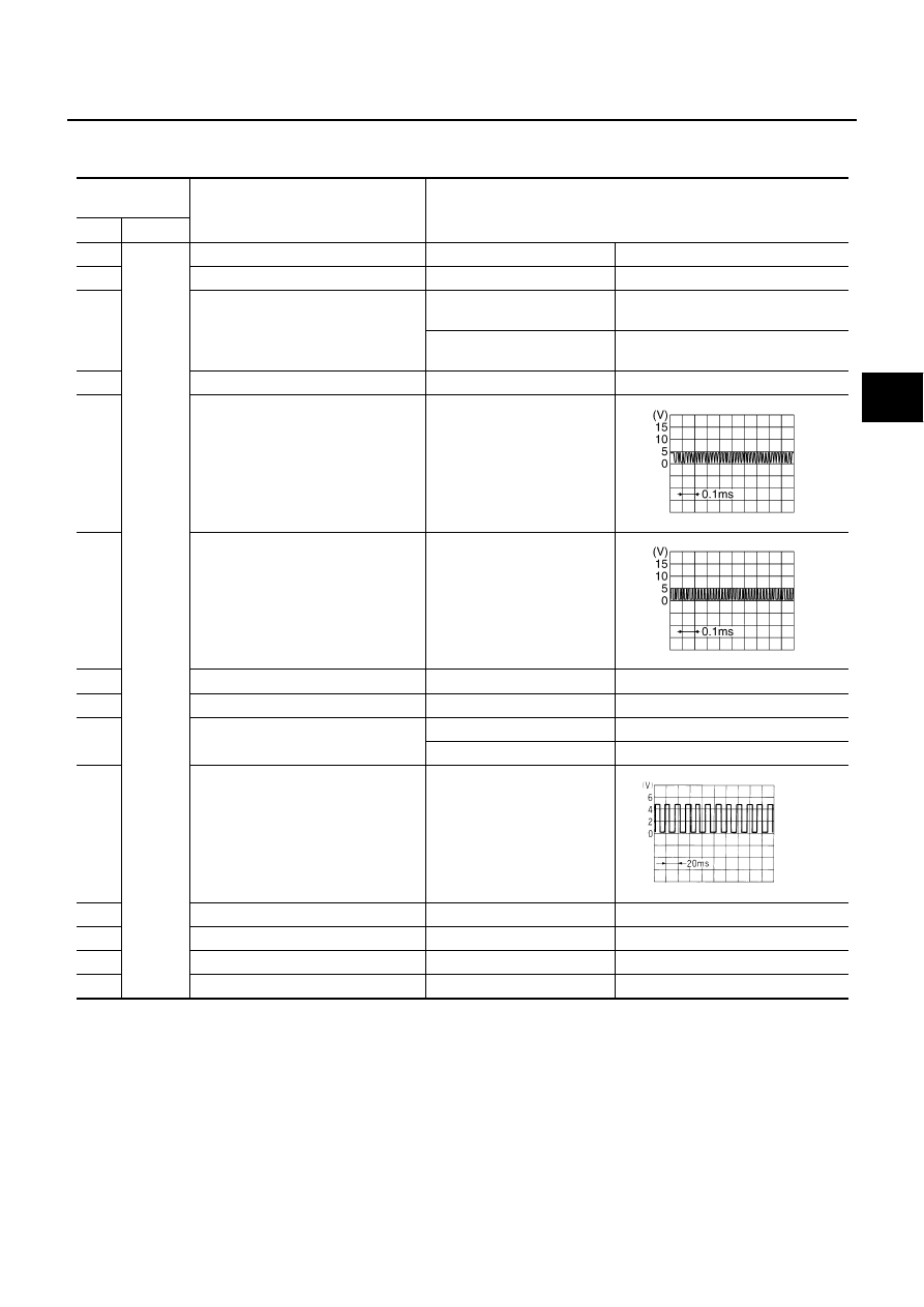
Control Unit Input/Output Signal Standard

AES0008B

Standards using a circuit tester and oscilloscope.

Measurement

terminal

Measuring point

Standard value

+

1

Ground

Battery Power supply

Always

Battery voltage (Approx. 12V)

2

Ignition switch ON or START

Ignition switch ON

Battery voltage (Approx. 12V)

3

Tire pressure warning lamp

Tire pressure warning lamp 
turns ON

Approx. 0V

Tire pressure warning lamp 
turns OFF

Battery voltage (Approx. 12V)

4

Ignition switch ON or ACC

Ignition switch ON

Battery voltage (Approx. 12V)

5

Communication line (+)

Always

6

Communication line (–)

Always

7

Communication line GND

Approx. 0V

8

Tire pressure warning check switch

Always

Approx. 5V

9

Combination flasher unit

Hazard lamp switch OFF

Battery voltage (Approx. 12V)

Hazard lamp switch ON

Approx. 0V

10

Vehicle speed signal
(8-pulse)

Combination meter operated
[When vehicle speed is 
approx. 40 km/h (25 MPH)]

11

GND

Approx. 0V

12

Data link connector (RX)

13

Data link connector (TX)

17

Antenna

SEIA0188E

SEIA0189E

ELF1084D

WT-14

TROUBLE DIAGNOSES

ID Registration Procedure

AES00043

ID REGISTRATION WITH TRANSMITTER ACTIVATION TOOL

1.

Turn ignition switch “OFF”.

2.

Connect CONSULT-II to data link connector.

3.

Start engine.

4.

Touch “START”, “AIR PRESSURE MONITOR”, “WORK SUPPORT” and “ID REGIST”.

5.

With the transmitter activation tool (J-45295) pushed against the
front-left transmitter, press the button then keep 5 seconds.

6.

Register the IDs in order from FR LH, FR RH, RR RH, to RR LH. When ID registration of each wheel has
been completed, a buzzer sounds and hazard warning lamp blinks.

7.

After completing all ID registrations, press “END” to complete the procedure.
NOTE:
Be sure to register the IDs in order from FR LH, FR RH, RR RH, to RR LH, or the self-diagnostic results
display will not function properly.

SEIA0460E

Activation tire position

Buzzer

Hazard warning lamp

CONSULT-II

1

FR  LH

Once

2 times flashing

“YET”

“DONE”

2

FR RH

2 times

3

RR RH

3 times

4

RR LH

4 times

TROUBLE DIAGNOSES

WT-15

C

D

F

G

H

I

J

K

L

M

A

B

WT

ID REGISTRATION WITHOUT TRANSMITTER ACTIVATION TOOL

1.

Turn ignition switch “OFF”.

2.

Connect CONSULT-II to data link connector.

3.

Touch “START”, “AIR PRESSURE MONITOR”, “WORK SUPPORT” and “ID REGIST”.

4.

Adjust the tire pressure to the values shown in the table below for ID registration, and drive the vehicle at
32 km/h (20 MPH) or more for a few minutes.

5.

After completing all ID registrations, press “END” to complete the procedure.

Transmitter Wake Up Operation

AES000DS

WITH TRANSMITTER ACTIVATION TOOL

1.

With the transmitter activation tool (J-45295) pushed against the
front-left transmitter, press the button then keep 5 seconds.

When ignition switch ON, then warning lamp is blinks as fol-
low diagram transmitter must be waken up.

2.

Register the IDs in order from FR LH, FR RH, RR RH or RR LH. When wake up of each wheel has been
completed, a hazard warning lamp blinks.

3.

After completing waking up of all transmitters, make sure tire pressure warning lamp go out.

Tire position

Tire pressure kPa (kg/cm

2

 , psi)

Front-Left

250 (2.5, 36)

Front-Right

230 (2.3, 33)

Rear-Right

210 (2.1, 30)

Rear-Left

190 (1.9, 27)

Activation tire position

CONSULT-II

FR LH

“YET”

“DONE”

FR RH

RR RH

RR LH

SEIA0460E

SEIA0351E

WT-16

TROUBLE DIAGNOSES

Self-Diagnosis

AES00044

DESCRIPTION

During driving, the low tire pressure warning system receives the signal transmitted from the transmitter
installed in each wheel, and gives alarms when the tire pressure becomes low. The control unit of this system
has pressure judgement and trouble diagnosis functions.

FUNCTION

When the low tire pressure warning system detects low inflation pressure or another unusual symptom, the
warning lamps in the combination meter comes on. To start the self-diagnostic results mode, ground the self-
diagnostic (check) terminal. The malfunction location is indicated by the warning lamp flashing and the buzzer
sounds.

CONSULT-II
CONSULT-II Application to Low Tire Pressure Warning System

×

 : Applicable

 – : Not applicable

Self-Diagnostic Results Mode

NOTE:
Before performing the self-diagnosis, be sure to register the ID. Or, the actual malfunction location may be different from that displayed
on CONSULT-II.

ITEM

SELF-DIAGNOSTIC RESULTS

DATA MONITOR

Front - Left transmitter

×

×

Front - Right transmitter

×

×

Rear - Left transmitter

×

×

Rear - Right transmitter

×

×

Warning lamp

×

Vehicle speed

×

Buzzer (in control unit)

×

Diagnostic item

Diagnostic item is detected when ···

FLAT - TIRE - FL
FLAT - TIRE - FR
FLAT - TIRE - RR
FLAT - TIRE - RL

Front-left tire pressure drops to 190 kPa(1.9 kg/cm

2

 , 27 psi) or less

Front-right tire pressure drops to 190 kPa(1.9 kg/cm

2

 , 27 psi) or less

Rear-right tire pressure drops to 190 kPa(1.9 kg/cm

2

 , 27 psi) or less

Rear-left tire pressure drops to 190 kPa(1.9 kg/cm

2

 , 27 psi) or less

[NO-DATA] - FL
[NO-DATA] - FR
[NO-DATA] - RR
[NO-DATA] - RL

Data from front-left transmitter cannot be received.
Data from front-right transmitter cannot be received.
Data from rear-right transmitter cannot be received.
Data from rear-left transmitter cannot be received.

[CHECKSUM- ERR] - FL
[CHECKSUM- ERR] - FR
[CHECKSUM- ERR] - RR
[CHECKSUM- ERR] - RL

Checksum data from front-left transmitter is malfunctioning.
Checksum data from front-right transmitter is malfunctioning.
Checksum data from rear-right transmitter is malfunctioning.
Checksum data from rear-left transmitter is malfunctioning.

[PRESSDATA- ERR] - FL
[PRESSDATA- ERR] - FR
[PRESSDATA- ERR] - RR
[PRESSDATA- ERR] - RL

Air pressure data from front-left transmitter is malfunctioning.
Air pressure data from front-right transmitter is malfunctioning.
Air pressure data from rear-right transmitter is malfunctioning.
Air pressure data from rear-left transmitter is malfunctioning.

[CODE- ERR] - FL
[CODE- ERR] - FR
[CODE- ERR] - RR
[CODE- ERR] - RL

Function code data from front-left transmitter is malfunctioning.
Function code data from front-right transmitter is malfunctioning.
Function code data from rear-right transmitter is malfunctioning.
Function code data from rear-left transmitter is malfunctioning.

[BATT - VOLT - LOW] - FL
[BATT - VOLT - LOW] - FR
[BATT - VOLT - LOW] - RR
[BATT - VOLT - LOW] - RL

Battery voltage of front-left transmitter drops.
Battery voltage of front-right transmitter drops.
Battery voltage of rear-right transmitter drops.
Battery voltage of rear-left transmitter drops.

RECEIVER- ID- NO- REG

No ID registration has been made to the tire pressure warning control unit.


Content   ..  800  801  802  803   ..