Infiniti M45 (Y34). Manual - part 766
AUTOMATIC DRIVE POSITIONER
SE-85
C
D
E
F
G
H
J
K
L
M
A
B
SE
3.
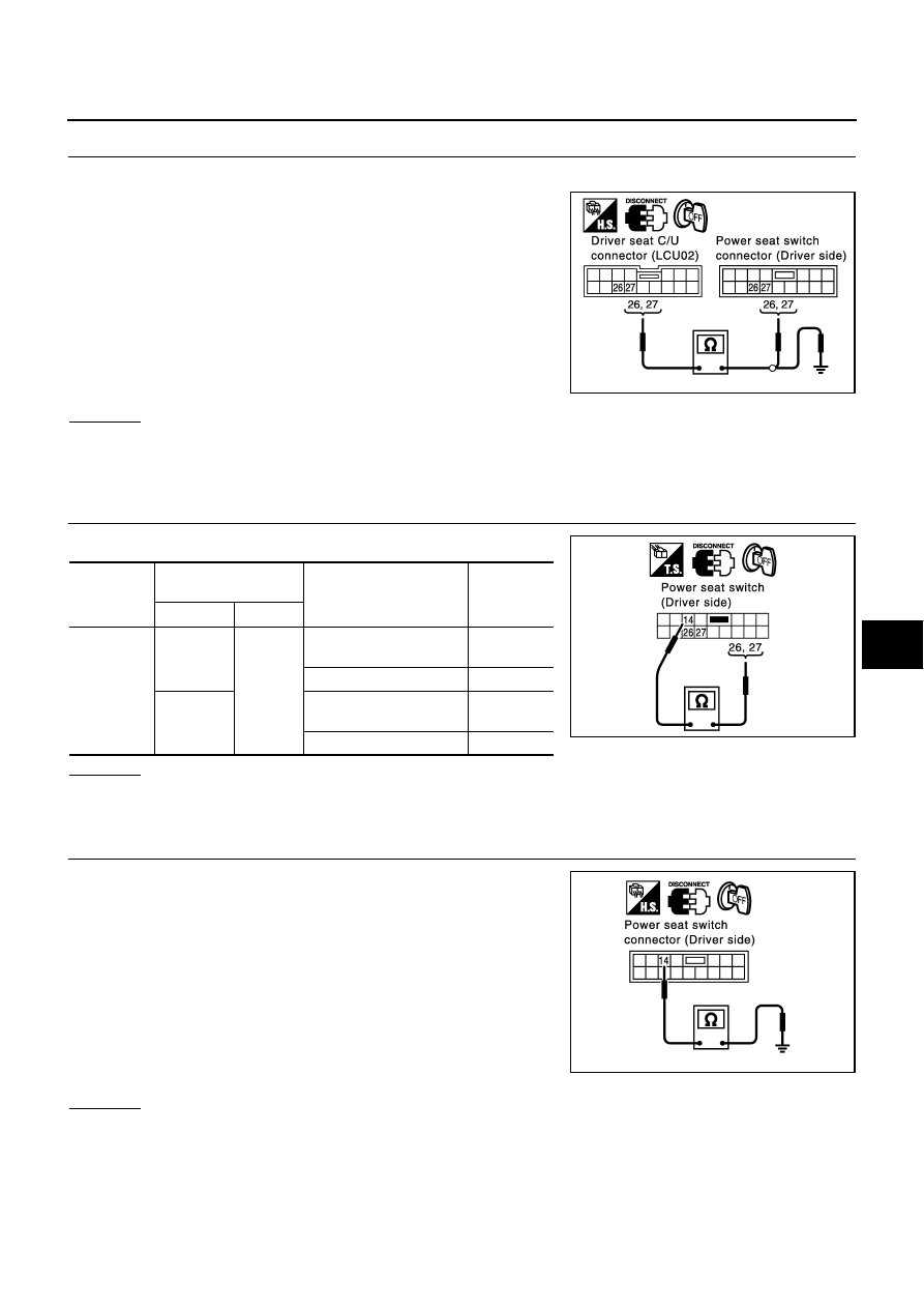
CHECK HARNESS CONTINUITY
1.
Disconnect driver seat control unit connector and driver power seat switch connector.
2.
Check continuity between driver seat control unit connector
B143 terminals 26 (P/B), 27 (B/Y) and power seat switch (driver
side) connector B144 terminals 26 (P/B), 27 (B/Y).
3.
Check continuity between driver seat control unit connector
B143 terminals 26 (P/B), 27 (B/Y) and body ground.
OK or NG
OK
>> GO TO 4.
NG
>> Repair or replace harness between driver seat control unit and driver power seat switch (driver
side).
4.
CHECK REAR END LIFTING SWITCH
Check continuity between driver seat switch.
OK or NG
OK
>> GO TO 5.
NG
>> Replace power seat switch (driver side).
5.
CHECK POWER SEAT SWITCH GROUND CIRCUIT
Check continuity between power seat switch connector B144 termi-
nal 14 (B/W) and body ground.
OK or NG
OK
>> Check the harness and connector.
NG
>> Repair or replace harness between power seat switch (driver side) and body ground.
26 (P/B) – 26 (P/B)
: Continuity should exist.
27 (B/Y) – 27 (P/Y)
: Continuity should exist.
26 (P/B) – Ground
: Continuity should not exist.
27 (B/Y) – Ground
: Continuity should not exist.
PIIA3304E
Connector
Terminals
(Wire color)
Condition
Continuity
(+)
(–)
B143
26 (P/B)
14 (B/W)
Rear lifting switch ON(UP
operation)
Yes
Rear lifting switch OFF
No
27 (B/Y)
Rear lifting switch ON
(DOWN operation)
Yes
Rear lifting switch OFF
No
PIIA4480E
14 (B/W) – Ground
: Continuity should exist.
PIIA3297E