Infiniti M45 (Y34). Manual - part 759
AUTOMATIC DRIVE POSITIONER
SE-57
C
D
E
F
G
H
J
K
L
M
A
B
SE
3.
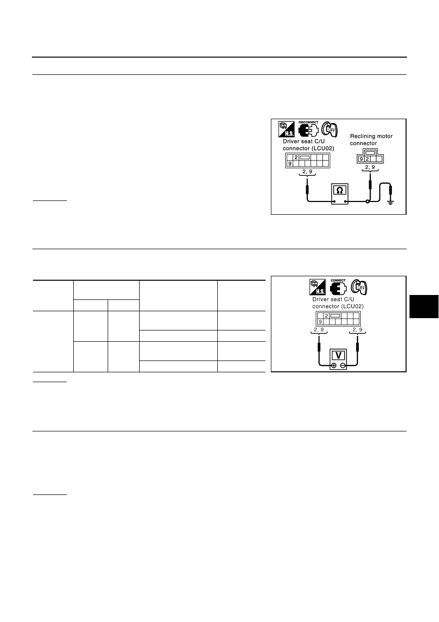
CHECK HARNESS CONTINUITY
1.
Turn ignition switch OFF.
2.
Disconnect driver seat control unit connector and reclining motor connector.
3.
Check continuity between driver seat control unit connector B142 terminals 2 (G), 9 (LG) and reclining
motor connector B147 terminals 2 (G), 9 (LG).
4.
Check continuity between driver seat control unit connector
B142 terminals 2 (G), 9 (LG) and body ground.
OK or NG
OK
>> GO TO 4.
NG
>> Repair or replace harness between driver seat control
unit and reclining motor.
4.
CHECK DRIVER SEAT CONTROL UNIT OUTPUT SIGNAL
1.
Connect the driver seat control unit and reclining motor connector.
2.
Check voltage between driver seat control unit connector.
OK or NG
OK
>> Replace reclining motor.
NG
>> Replace driver seat control unit.
Front End Seat Lifting Motor Circuit Inspection
AIS001JY
1.
CHECK FRONT END SEAT LIFTING MECHANISM
Check the following.
1.
Operation malfunction caused by lifter mechanism deformation or pinched harness or other foreign mate-
rials.
2.
Operation malfunction caused by foreign materials adhered to the lifter motor or lead screws.
3.
Operation malfunction and interference with other parts by installation.
OK or NG
OK
>> GO TO 2.
NG
>> Repair the malfunctioning part and check again.
2 (G) – 2 (G)
: Continuity should exist.
9 (LG) – 9 (LG)
: Continuity should exist.
2 (G) – Ground
: Continuity should not exist.
9 (LG) – Ground
: Continuity should not exist.
PIIA2923E
Connector
Terminals
(Wire color)
Condition
Voltage (V)
(Approx)
(+)
(–)
B142
2 (G)
9 (LG)
Reclining switch
(FR operation)
Battery voltage
Reclining switch OFF
0
9 (LG)
2 (G)
Reclining switch
(RR operation)
Battery voltage
Reclining switch OFF
0
PIIA2924E