Infiniti M45 (Y34). Manual - part 739
BATTERY
SC-7
C
D
E
F
G
H
I
J
L
M
A
B
SC
1.
Turn off all loads on the vehicle electrical system. Clean or repair
as necessary.
2.
Visually inspect the battery, battery terminals and cable ends
with ignition switch in “OFF” position.
NOTE:
The contact surface between the battery terminals, cable ends
and tester leads must be clean for a valid test. A poor connec-
tion will prevent testing and a “CHECK CONNECTION” mes-
sage will appear during the test procedures. If this occurs, clean
the battery post and terminals, reconnect them and restart the
test.
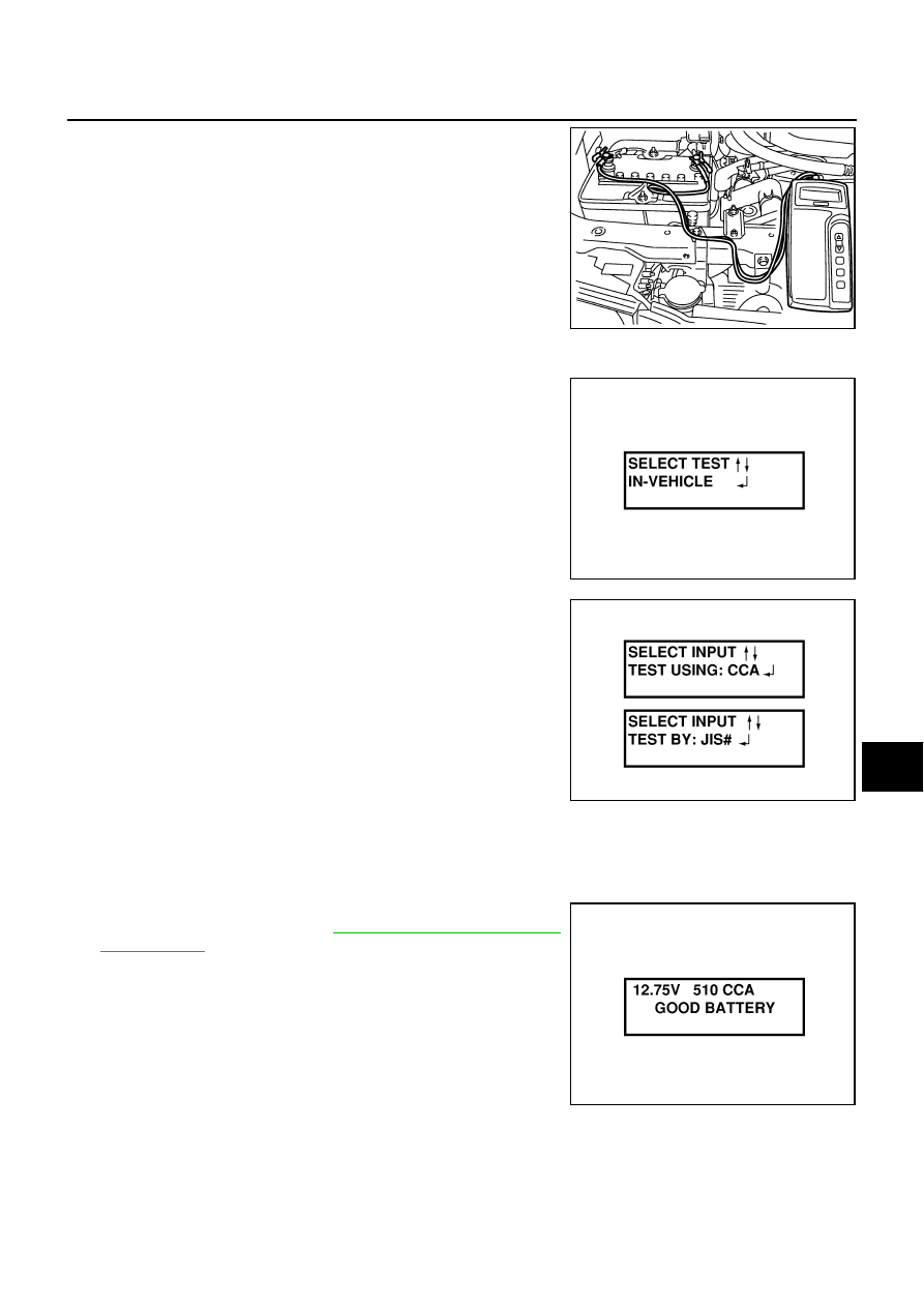
3.
Connect the red tester lead clamp to the positive battery termi-
nal, and the black to the negative terminal.
4.
The tester will turn on automatically. Using the arrow keys,
select “IN VEHICLE” on the tester and then press the “ENTER”
key.
5.
Locate the battery type and rating stamped or written on the top
case of the battery to be tested.
NOTE:
The battery type and rating will have either of the following.
CCA: Cold Cranking Amps (490 CCA, 550 CCA, etc.)
JIS: Japanese Industrial Standard.
Battery is stamped with a number such as:
80D26L: 80 (rank of output), D (physical size-depth), 26 (width
in cm). The last character L (post configuration) is not input into
the tester.
The tester requires the rating for the battery be entered exactly
as it is written or stamped on the battery. Do not attempt a CCA
conversion for JIS stamped batteries. JIS must be input directly.
6.
Using the arrow and “ENTER” keys alternately, select the battery type and rating.
NOTE:
The tester lists five choices; CCA, JIS, IEC, DIN, and EN. Only use CCA or JIS.
7.
Press “ENTER” to begin the test. Diagnosis results are dis-
played on the tester. Refer to
.
SEL404X
SEL405X
SEL406X
SEL407X