Infiniti M45 (Y34). Manual - part 724


  Index      Infiniti     Infiniti M45 (Y34) - service repair manual 2004 year


Search            copyright infringement  


Content   ..  722  723  724  725   ..


Infiniti M45 (Y34). Manual - part 724


SIDE OIL SEAL

RFD-9

C

E

F

G

H

I

J

K

L

M

A

B

RFD

SIDE OIL SEAL

PFP:33142

Removal and Installation

ADS0001K

REMOVAL

1.

Remove side flange with the following procedure for press-fitting.

a.

Remove rear wheel sensor. Refer to 

BRC-63, "Removal and Installation"

 .

b.

Remove drive shaft and axle assembly. Refer to 

RAX-10, "REAR DRIVE SHAFT"

  an

RAX-6, "WHEEL

HUB"

 .

c.

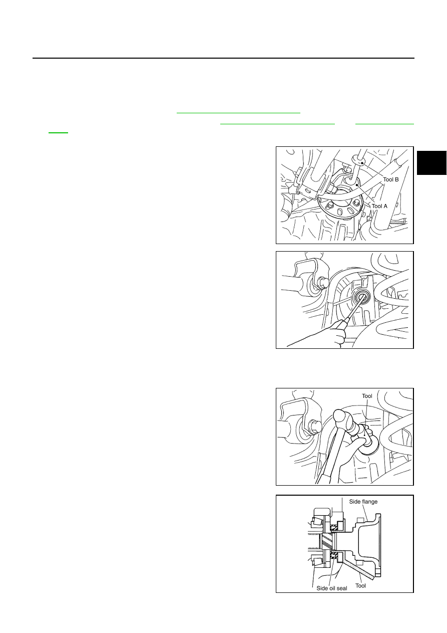
Install axle stand to side flange.

d.

Using a sliding hammer, pull out the side flange.

2.

Remove oil seal using a flat-bladed screwdriver.

INSTALLATION

1.

Apply multi-purpose grease to sealing lips of side oil seal.

2.

Using the drift, press-fit oil seal so that its surface comes face to
face with the end surface of the case.

CAUTION:

When installing the oil seal be careful not to get it
inclined.

Discard the old oil seal. Always replace with new one.

3.

Install the side flange with the following procedure.

a.

Attach the protector to side oil seal.

b.

After the side flange is inserted and the serrated part of side
gear has engaged the serrated part of flange, remove the pro-
tector.

Tool number A

: KV40104100 ( – )

Tool number B

: ST3623000 (J25840-A)

SDIA1005E

SDIA1036E

Tool number

: KV38100200 (J26233)

SDIA1037E

Tool number

: KV38107900 (J39352)

SDIA0822E

RFD-10

SIDE OIL SEAL

c.

Put suitable drift on the center of side flange, then drive it until
sound changes.

NOTE:
When installation is completed, driving sound of the side flange
turns into a sound which seems to affect the whole final drive.

4.

Confirm that the dimension of the side flange installation (Mea-
surement A) in the illustration comes into the following.

5.

Install the drive shaft and axle assembly. Refer to 

RAX-10,

"REAR DRIVE SHAFT"

  an

RAX-6, "WHEEL HUB"

 .

6.

Align the installing position of the wheel sensor. Refer to 

BRC-63, "Removal and Installation"

 .

Measurement A

: Approx. 326 - 328 mm (12.83 - 12.91 in)

SDIA1039E

REAR FINAL DRIVE ASSEMBLY

RFD-11

C

E

F

G

H

I

J

K

L

M

A

B

RFD

REAR FINAL DRIVE ASSEMBLY

PFP:38300

Removal and Installation

ADS0001L

REMOVAL

1.

Remove exhaust center tube with power tool. Refer to 

EX-3, "EXHAUST SYSTEM"

 .

2.

Remove rear cross bar with power tool. Refer to 

RSU-7, "Components"

 .

3.

Remove rear stabilizer bar with power tool. Refer to 

RSU-15, "STABILIZER BAR"

 .

4.

Remove rear propeller shaft from the final drive. Refer to 

PR-5, "Removal and Installation"

 .

5.

Remove rear drive shaft from final drive, then suspend it by wire etc. with power tool.

6.

Remove breather hose from the final drive.

7.

Remove rear wheel sensor. Refer to 

BRC-63, "WHEEL SENSORS"

 .

8.

Place a transmission jack on the final drive.

CAUTION:

Do not place a transmission jack on the rear cover (aluminum case).

9.

Remove the mounting bolts and nuts connecting to the suspension member, and remove the rear final
drive.

INSTALLATION

Install in the reverse order of removal.

CAUTION:

After installation, check the final drive oil level. Refer to 

MA-21, "Checking Differential Gear Oil"

 .

1.

Breather hose

2.

Gear carrier

3.

Clip

4.

Rear propeller shaft

5.

Washer

6.

Lower stopper

7.

Drive shaft

8.

Rear final drive assembly

9.

Upper stopper

PDIA0882E

RFD-12

REAR FINAL DRIVE ASSEMBLY

Components

ADS0001M

R200 2–PINION

PDIA0087E


Content   ..  722  723  724  725   ..