Infiniti M45 (Y34). Manual - part 706
POWER STEERING GEAR AND LINKAGE
PS-15
C
D
E
F
H
I
J
K
L
M
A
B
PS
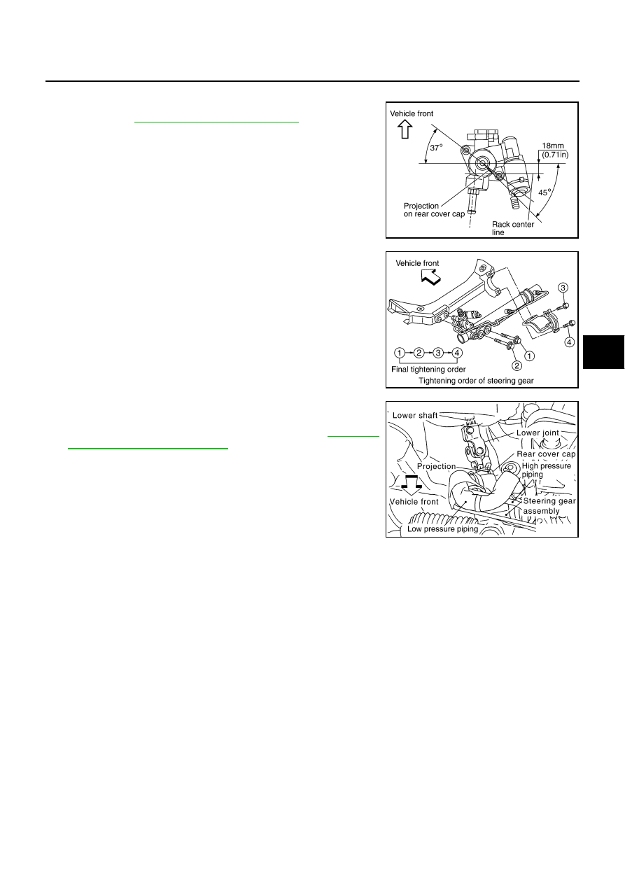
INSTALLATION
In following items with care, install components in reverse order of
removal. Refer to
PS-13, "Removal and Installation"
●
Confirm rear cover cap on steering gear consists with steering
gear when front wheels are set in straight ahead direction as
shown in figure.
●
Tighten steering gear assembly as shown in figure.
●
Confirm if slit of lower yoke of lower joint fits with projection on
rear cover cap.
●
After installation, bleed air from piping. Refer to
Bleeding from Hydraulic System"
.
INSPECTION AFTER INSTALLATION
●
Check if steering wheel turns smoothly when it is turned several times fully to end of left and right.
SGIA0402E
SGIA0404E
SGIA0392E