Infiniti M45 (Y34). Manual - part 702
REAR PROPELLER SHAFT
PR-7
C
E
F
G
H
I
J
K
L
M
A
B
PR
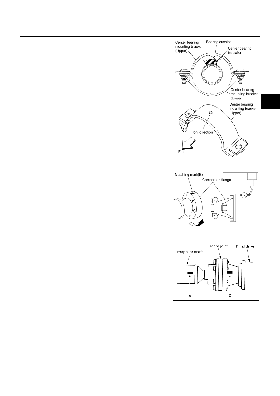
b.
Adjust position of the bearing cushion so as not to apply thrust
play to the center bearing insulator.
c.
Position the bearing cushion overlap as shown in the figure.
d.
Install the center bearing bracket (upper) with its arrow mark fac-
ing forward.
e.
Tighten the center bearing mounting bracket (upper) fixing nuts
to specified torque.
CAUTION:
Do not reuse the nuts. Always replace the nuts with a new
one.
2.
If companion flange has been removed, put new alignment
matching mark B on it. Then, reassemble using the following
procedure.
Perform these steps when either of final drive and shaft is
replaced with a new one.
a.
Erase original mark B from companion flange with suitable sol-
vent.
b.
Measure companion flange vertical runout.
c.
Determine the position where maximum runout is read on dial
indicator. Put mark (shown by B in figure) on flange perimeter
corresponding to maximum runout position.
3.
If the propeller shaft or final drive has been replaced, connect
the propeller shaft and final drive as follows:
NOTE:
Avoid damaging the rebro joint boot, protect it with a shop towel
or equivalent.
●
Install the propeller shaft while aligning its matching mark A
with the mark C on the joint as close as possible.
●
Tighten the joint bolts/nuts to specified torque.
CAUTION:
Do not reuse the bolts, and washers. Always replace
them with new ones.
●
After installation, check the vibration by driving the vehicle. If the vibration is present, remove the pro-
peller shaft from the final drive companion flange.
●
Turn the propeller shaft 60, 120, 180, 240 or 300 degrees and reinstall the propeller shaft to the com-
panion flange, then measure the runout again by driving the vehicle on each angle position.
PDIA0017E
SDIA2060E
SDIA0768E