Infiniti M45 (Y34). Manual - part 665
STEP LAMP
LT-167
C
D
E
F
G
H
I
J
L
M
A
B
LT
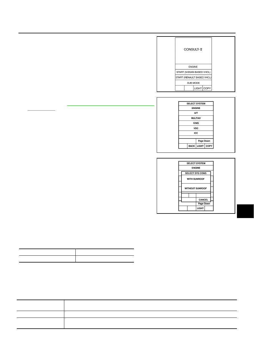
2.
Touch “START (NISSAN BASED VHCL)”.
3.
Touch “IVMS” on “SELECT SYSTEM” screen. If “IVMS” is not
indicated, refer to
GI-38, "CONSULT-II Data Link Connector
4.
Check the model specification, touch either “WITH SUNROOF”
or “WITHOUT SUNROOF”.
5.
Touch “OK”. If the selection is wrong, touch “CANCEL”.
6.
Select the desired part to be diagnosed on
“SELECT TEST ITEM” screen.
DATA MONITOR
Operation Procedure
1.
Touch “STEP LAMP” on “SELECT TEST ITEM” screen.
2.
Touch “DATA MONITOR” on “SELECT DIAG MODE” screen.
3.
Touch “ALL SIGNALS” or “SELECTION FROM MENU” on “DATA MONITOR” screen.
4.
Touch “START”.
5.
When selected “SELECTION FROM MENU”, touch items to be monitored. When “ALL SIGNALS” is
selected all items will be monitored.
6.
Touch “RECORD” while monitoring and status of the item being monitored can be recorded. To stop
recording, touch “STOP”.
Data Monitor Item
SKIA3098E
SKIA3783E
PIIA0184E
MAIN SIGNALS
Monitors the main items.
SELECTION FROM MENU
Selects and monitors the items.
Monitored item
[“OPERATION or UNIT”]
Description
DOOR SW-DR
[ON/OFF]
Displays “Door open (ON)/door closed (OFF)” status judged from the front door switch (driver side) signal.
DOOR SW-AS
[ON/OFF]
Displays “Door open (ON)/door closed (OFF)” status judged from the front door switch (passenger side)
signal.