Infiniti M45 (Y34). Manual - part 664
STEP LAMP
LT-163
C
D
E
F
G
H
I
J
L
M
A
B
LT
Terminals and Reference Value for Driver Door Control Unit (LCU 01)
AKS004DH
Terminals and Reference Value for Passenger and Rear LH, RH Door Control
Unit
AKS002H2
*: Rear LH door control unit and rear RH control unit
Terminals and Reference Value for BCM
AKS004DI
Terminal
No.
Wire
color
Item
Operation or condition
Reference value
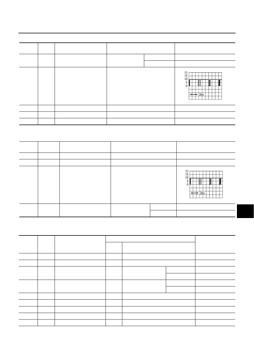
3
R
Step lamp
Each door switch
ON (open)
Approx. 0V
OFF (closed)
Battery voltage
5
L/Y
Local data line
—
8
G/W
Data line A-3
—
—
14
Y/G
Power source (PTC)
—
Battery voltage
15
B
Ground
—
Approx. 0V
SIIA0591J
Terminal
No.
Wire color
Item
Operation or condition
Reference value
10
W/R (Y/B)*
Power source (PTC)
—
Battery voltage
11
B
Ground
—
Approx. 0V
15
L/Y
Local data line
—
16
R (R/W)*
Step lamp
Each door switch
ON (open)
Approx. 0V
OFF (closed)
Battery voltage
SIIA0591J
Terminal
No.
Wire
color
Signal description
Measuring condition
Reference value
Ignition
switch
Operation or condition
17
BR/Y
Data link RX
—
—
—
18
P
Data link TX
—
—
—
33
W
Door lock assembly rear LH
(door switch) signal
OFF
Door lock assembly rear
LH (door switch)
ON (open)
Approx. 0V
OFF (closed)
Battery voltage
37
LG
Front door switch (passen-
ger side) signal
OFF
Front door switch (pas-
senger side)
ON (open)
Approx. 0V
OFF (closed)
Battery voltage
56
B
Ground
—
—
Approx. 0V
67
G/W
Data line A-3
—
—
—
68
W/B
Ignition switch ON or START
ON
—
Battery voltage
105
Y/L
Battery power supply
OFF
—
Battery voltage
113
B
Ground
—
—
Approx. 0V