Infiniti M45 (Y34). Manual - part 660


  Index      Infiniti     Infiniti M45 (Y34) - service repair manual 2004 year


Search            copyright infringement  


Content   ..  658  659  660  661   ..


Infiniti M45 (Y34). Manual - part 660


INTERIOR ROOM LAMP

LT-147

C

D

E

F

G

H

I

J

L

M

A

B

LT

2. 

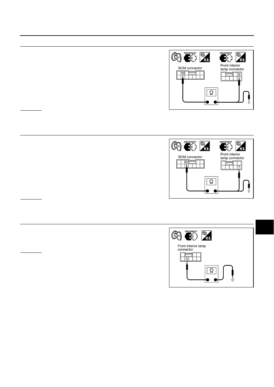
CHECK INTERIOR LAMP ILL SWITCH TOTAL ILL CIRCUIT

1.

Disconnect front interior lamp connector.

2.

Check continuity between BCM harness connector R4 terminal
130 (W/L) and front interior lamp harness connector R6 terminal
6 (W/L).

3.

Check continuity between BCM harness connector R4 terminal
130 (W/L) and ground.

OK or NG

OK

>> GO TO 3.

NG

>> Repair harness or connector.

3. 

CHECK INTERIOR LAMP ILL SWITCH ALL OFF CIRCUIT

1.

Disconnect front interior lamp connector.

2.

Check continuity between BCM harness connector R4 terminal
131 (G/Y) and front interior lamp harness connector R6 terminal
7 (G/Y).

3.

Check continuity between BCM harness connector R4 terminal
131 (G/Y) and ground.

OK or NG

OK

>> GO TO 4.

NG

>> Repair harness or connector.

4. 

CHECK INTERIOR LAMP ILL SWITCH GROUND CIRCUIT

Check continuity between front interior lamp harness connector R6
terminal 3 (B) and ground.

OK or NG

OK

>> Replace front interior lamp.

NG

>> Check harness ground circuit.

130 (W/L) - 6 (W/L)

: Continuity should exist.

130 (W/L) - Ground

: Continuity should not exist.

PKIA5953E

131 (G/Y) - 7 (G/Y)

: Continuity should exist.

131 (G/Y) - Ground

: Continuity should not exist.

PKIA5954E

3 (B) - Ground

: Continuity should exist.

PKIA5955E

LT-148

INTERIOR ROOM LAMP

Personal Lamp Switch System Inspection

AKS002GR

1. 

CHECK PERSONAL LAMP SWITCH SIGNAL

1.

Turn ignition switch OFF.

2.

Disconnect BCM connector.

3.

Check continuity between BCM harness connector R4 terminal
129 (G) and ground while operating the personal lamp switch.

OK or NG

OK

>> Personal lamp switch is OK.

NG

>> GO TO 2.

2. 

CHECK PERSONAL LAMP SWITCH CIRCUIT

1.

Disconnect rear interior lamp connector.

2.

Check continuity between BCM harness connector R4 terminal
129 (G) and rear interior lamp harness connector R13 terminal 5
(G).

3.

Check continuity between BCM harness connector R4 terminal
129 (G) and ground.

OK or NG

OK

>> GO TO 3.

NG

>> Repair harness or connector.

3. 

CHECK PERSONAL LAMP SWITCH GROUND CIRCUIT

Check continuity between rear interior lamp harness connector R13
terminal 3 (B) and ground.

OK or NG

OK

>> Replace rear interior lamp.

NG

>> Repair harness.

Terminals

RH, LH 

personal lamp switch 

position

Continuity

Connector

Terminal (Wire color)

R4

129 (G)

Ground

HALF or AUTO

No

FULL

Yes

PKIA5956E

129 (G) - 5 (G)

: Continuity should exist.

129 (G) - Ground

: Continuity should not exist.

PKIA5957E

3 (B) - Ground

: Continuity should exist.

PKIA5958E

INTERIOR ROOM LAMP

LT-149

C

D

E

F

G

H

I

J

L

M

A

B

LT

Door Switch System Inspection

AKS002GS

1. 

CHECK DOOR SWITCH SIGNAL

With CONSULT-II

Operate each door via “DOOR SW” on “DATA MONITOR”
screen and make sure that the switch turns on and off as com-
manded.

Without CONSULT-II

Operate each door and via “switch monitor” of the self-diagnosis
function and make sure that the switch turns on and off as com-
manded.

OK or NG

OK

>> Door switch is OK.

NG

>> GO TO 2.

2. 

CHECK FRONT DOOR SWITCH (DRIVER SIDE) CIRCUIT

1.

Turn ignition switch OFF.

2.

Disconnect BCM connector and front door switch (driver side)
connector.

3.

Check continuity between BCM harness connector B4 terminal
142 (R/Y) and front door switch (driver side) harness connector
B20 terminal 1 (R/Y).

4.

Check continuity between BCM harness connector B4 terminal
142 (R/Y) and ground.

NOTE:
If front door switch (driver side) is normal, skip this procedure and go to 3.

OK or NG

OK

>> GO TO 3.

NG

>> Repair harness or connector.

3. 

CHECK FRONT DOOR SWITCH (PASSENGER SIDE) CIRCUIT

1.

Disconnect front door switch (passenger side) connector.

2.

Check continuity between BCM harness connector M4 terminal
37 (LG) and front door switch (passenger side) harness connec-
tor B220 terminal 1 (LG).

3.

Check continuity between BCM harness connector M4 terminal
37 (LG) and ground.

NOTE:
If front door switch (passenger side) is normal, skip this procedure
and go to 4.

OK or NG

OK

>> GO TO 4.

NG

>> Repair harness or connector.

SKIA0441E

142 (R/Y) - 1 (R/Y)

: Continuity should exist. 

142 (R/Y) - Ground

: Continuity should not exist.

PKIA5959E

37 (LG) - 1 (LG)

: Continuity should exist. 

37 (LG) - Ground

: Continuity should not exist.

PKIA5960E

LT-150

INTERIOR ROOM LAMP

4. 

CHECK DOOR LOCK ASSEMBLY REAR LH (DOOR SWITCH) CIRCUIT

1.

Disconnect door lock assembly rear LH connector.

2.

Check continuity between BCM harness connector M4 terminal
33 (W) and door lock assembly rear LH harness connector D62
terminal 1 (W).

3.

Check continuity between BCM harness connector M4 terminal
33 (W) and ground.

NOTE:
If door lock assembly rear LH (door switch) is normal, skip this pro-
cedure and go to 5.

OK or NG

OK

>> GO TO 5.

NG

>> Repair harness or connector.

5. 

CHECK DOOR LOCK ASSEMBLY REAR RH (DOOR SWITCH) CIRCUIT

1.

Disconnect door lock assembly rear RH connector.

2.

Check continuity between BCM harness connector B4 terminal
143 (W/L) and door lock assembly rear RH harness connector
D82 terminal 1 (W).

3.

Check continuity between BCM harness connector B4 terminal
143 (W/L) and ground.

NOTE:
If door lock assembly rear RH (door switch) is normal, skip this pro-
cedure and go to 6.

OK or NG

OK

>> GO TO 6.

NG

>> Repair harness or connector.

6. 

CHECK DOOR SWITCH

1.

Check front door switch.

2.

Check continuity between door lock assembly rear LH, RH (door
switch) connector D62, D82 terminals 1 and 2 while turning the
door switches ON (open) and OFF (closed).

OK or NG

OK

>> Check front door switch case ground condition or door

lock assembly rear LH, RH (door switch) ground circuit.

NG

>> Replace the door switch.

33 (W) - 1 (W)

: Continuity should exist. 

33 (W) - Ground

: Continuity should not exist.

PKIA5961E

143 (W/L) - 1 (W)

: Continuity should exist. 

143 (W/L) - Ground

: Continuity should not exist.

PKIA5962E

Switch released (ON)

: Continuity should exist.

Switch pressed (OFF)

: Continuity should not exist.

Connector

Terminal

Condition

Continuity

D62

1

2

ON (Door open)

Yes

D82

OFF (Door closed)

No

PKIA5964E


Content   ..  658  659  660  661   ..