Infiniti M45 (Y34). Manual - part 648


  Index      Infiniti     Infiniti M45 (Y34) - service repair manual 2004 year


Search            copyright infringement  


Content   ..  646  647  648  649   ..


Infiniti M45 (Y34). Manual - part 648


TURN SIGNAL AND HAZARD WARNING LAMPS

LT-99

C

D

E

F

G

H

I

J

L

M

A

B

LT

Front Turn Signal Lamp LH or RH Does Not Operate 

AKS003VA

1. 

CHECK BULB

1.

Replace bulb with other side bulb or new one.

2.

Check if front turn signal lamp illuminates correctly.

OK or NG

OK

>> Replace combination flasher unit.

NG

>> GO TO 2.

2. 

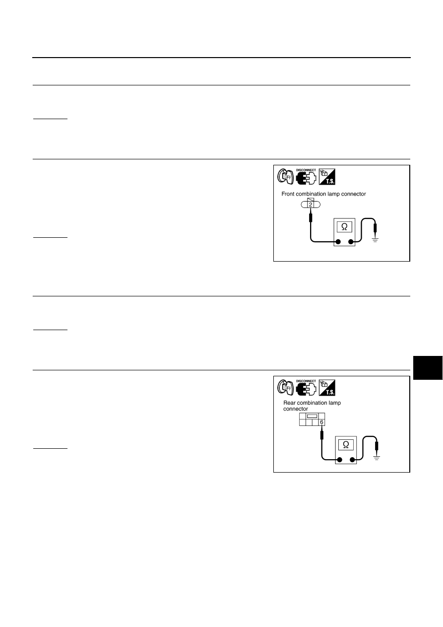
CHECK FRONT COMBINATION LAMP GROUND CIRCUIT

1.

Turn ignition switch OFF. 

2.

Disconnect front combination lamp connector.

3.

Check continuity between front combination lamp LH harness
connector E12 terminal 2 (B), and front combination lamp RH
harness connector E50 terminal 2 (B) and ground. 

OK or NG

OK

>> Check harness for open or short between front combi-

nation lamp and combination switch.

NG

>> Repair harness.

Rear Turn Signal Lamp LH or RH Does Not Operate

AKS003VB

1. 

CHECK BULB

1.

Replace bulb with other side bulb or new one.

2.

Check if rear turn signal lamp illuminates correctly.

OK or NG

OK

>> Replace combination flasher unit.

NG

>> GO TO 2.

2. 

CHECK REAR COMBINATION LAMP GROUND CIRCUIT

1.

Turn ignition switch OFF. 

2.

Disconnect rear combination lamp connector.

3.

Check continuity between rear combination lamp LH harness
connector B53 terminal 6 (B), and rear combination lamp RH
harness connector B58 terminal 6 (B) and ground.

OK or NG

OK

>> Check harness for open or short between front combi-

nation lamp and combination switch.

NG

>> Repair harness.

2 (B) - Ground

: Continuity should exist.

PKIA5925E

6 (B) - Ground

: Continuity should exist.

PKIA5926E

LT-100

TURN SIGNAL AND HAZARD WARNING LAMPS

LH and RH Turn Indicators Do Not Operate

AKS003ZL

1. 

CHECK COMBINATION METER GROUND CIRCUIT

1.

Turn ignition switch OFF.

2.

Disconnect combination meter connector.

3.

Check continuity between combination meter harness connector
M42 terminal 45 (B) and ground. 

OK or NG

OK

>> Replace combination meter.

NG

>> Repair harness.

LH or RH Turn Indicator Does Not Operate 

AKS003ZM

1. 

CHECK COMBINATION METER GROUND CIRCUIT

1.

Turn ignition switch OFF.

2.

Disconnect combination meter connector.

3.

Check continuity between combination meter harness connector
M42 terminal 45 (B) and ground. 

OK or NG

OK

>>

When LH turn indicator does not operate, GO TO 2.

When RH turn indicator does not operate, GO TO 3.

NG

>> Repair harness.

2. 

CHECK COMBINATION METER LH INDICATOR POWER SUPPLY CIRCUIT

1.

Disconnect combination switch connector.

2.

Check continuity between combination meter harness connector
M41 terminal 19 (P) and combination switch harness connector
M55 terminal 3 (G/R).

3.

Check continuity between combination meter harness connector
M41 terminal 19 (P) and ground.

OK or NG

OK

>> Replace combination meter.

NG

>> Repair harness or connector.

45 (B) - Ground

: Continuity should exist.

PKIA5927E

45 (B) - Ground

: Continuity should exist.

PKIA5927E

19 (P) - 3 (G/R)

: Continuity should exist.

19 (P) - Ground

: Continuity should not exist.

PKIA5928E

TURN SIGNAL AND HAZARD WARNING LAMPS

LT-101

C

D

E

F

G

H

I

J

L

M

A

B

LT

3. 

CHECK COMBINATION METER RH INDICATOR POWER SUPPLY CIRCUIT

1.

Disconnect combination switch connector.

2.

Check continuity between combination meter harness connector
M42 terminal 41 (G/Y) and combination switch harness connec-
tor M55 terminal 2 (G/OR).

3.

Check continuity between combination meter harness connector
M42 terminal 41 (G/Y) and ground.

OK or NG

OK

>> Replace combination meter.

NG

>> Repair harness or connector.

Electrical Components Inspection

AKS002FX

COMBINATION FLASHER UNIT CHECK

Before checking, ensure that bulbs meet specifications.

Connect a battery and test lamp to the combination flasher unit,
as shown. Combination flasher unit is properly functioning if it
blinks when power is supplied to the circuit.

Bulb Replacement

AKS002FY

FRONT TURN SIGNAL LAMP

Refer to 

LT-41, "Bulb Replacement"

  in “HEADLAMP (USA)”.

REAR TURN SIGNAL LAMP

Refer to 

LT-125, "REAR COMBINATION LAMP"

  in “PARKING, LICENSE PLATE AND TAIL LAMPS”.

Removal and Installation 

AKS002FZ

FRONT TURN SIGNAL LAMP

Refer to 

LT-42, "Removal and Installation"

  in “HEADLAMP (USA)”.

SIDE TURN SIGNAL LAMP

Refer to 

GW-118, "Disassembly and Assembly"

  in “GLASSES, WINDOW SYSTEM & MIRRORS (GW)” sec-

tion.

REAR TURN SIGNAL LAMP

Refer to 

LT-127, "REAR COMBINATION LAMP"

  in “PARKING, LICENSE PLATE AND TAIL LAMPS”.

41 (G/Y) - 2 (G/OR)

: Continuity should exist.

 41 (G/Y) - Ground

: Continuity should not exist.

PKIA5929E

PKIA5930E

LT-102

LIGHTING AND TURN SIGNAL SWITCH

LIGHTING AND TURN SIGNAL SWITCH

PFP:25540

Removal and Installation

AKS002G0

1.

Remove steering column cover. Refer to 

IP-11, "WORK STEPS"

in “IP” section.

2.

Remove lighting and turn signal switch mounting screws and
remove lighting and turn signal switch from spiral cable.

3.

Disconnect lighting and turn signal switch connector.

Switch Circuit Inspection

AKS002G1

Using circuit tester, check continuity between the lighting and turn signal switch connector terminals in each
operation status of the switch.

    Hi: “HIGH BEAM” position, Lo: “LOW BEAM” position, P: “FLASH TO PASS” position

PKIA2249E

SKIA0469E


Content   ..  646  647  648  649   ..