Infiniti M45 (Y34). Manual - part 642
HEADLAMP AIMING CONTROL
LT-75
C
D
E
F
G
H
I
J
L
M
A
B
LT
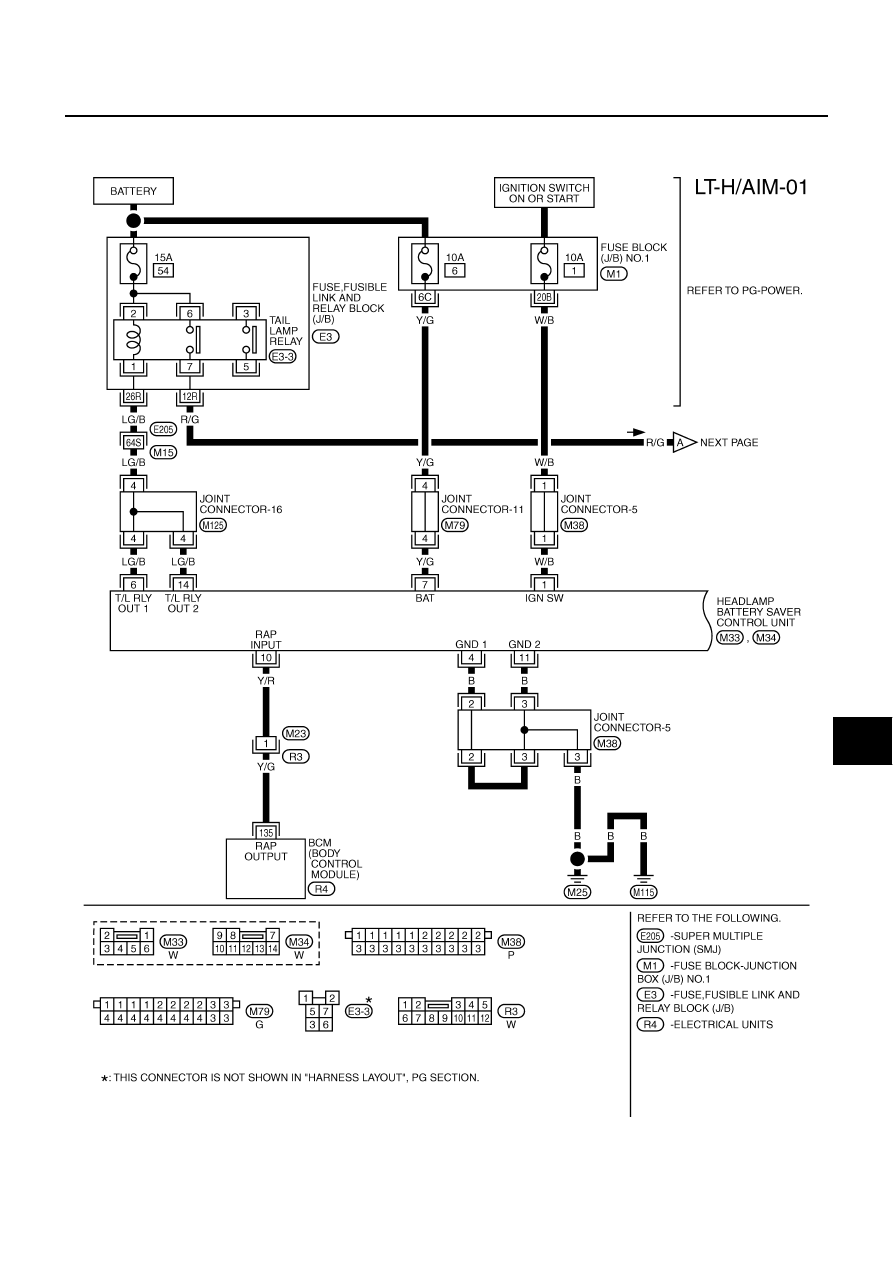
HEADLAMP AIMING CONTROL
PFP:26010
Wiring Diagram — H/AIM —
AKS002FQ
TKWA0533E
|
|
|
HEADLAMP AIMING CONTROL LT-75 C D E F G H I J L M A B LT HEADLAMP AIMING CONTROL PFP:26010 Wiring Diagram — H/AIM — AKS002FQ TKWA0533E |