Infiniti M45 (Y34). Manual - part 629


  Index      Infiniti     Infiniti M45 (Y34) - service repair manual 2004 year


Search            copyright infringement  


Content   ..  627  628  629  630   ..


Infiniti M45 (Y34). Manual - part 629


HEADLAMP (FOR USA)

LT-23

C

D

E

F

G

H

I

J

L

M

A

B

LT

SWITCH MONITOR

Perform the diagnosis on the switch system to each control unit.

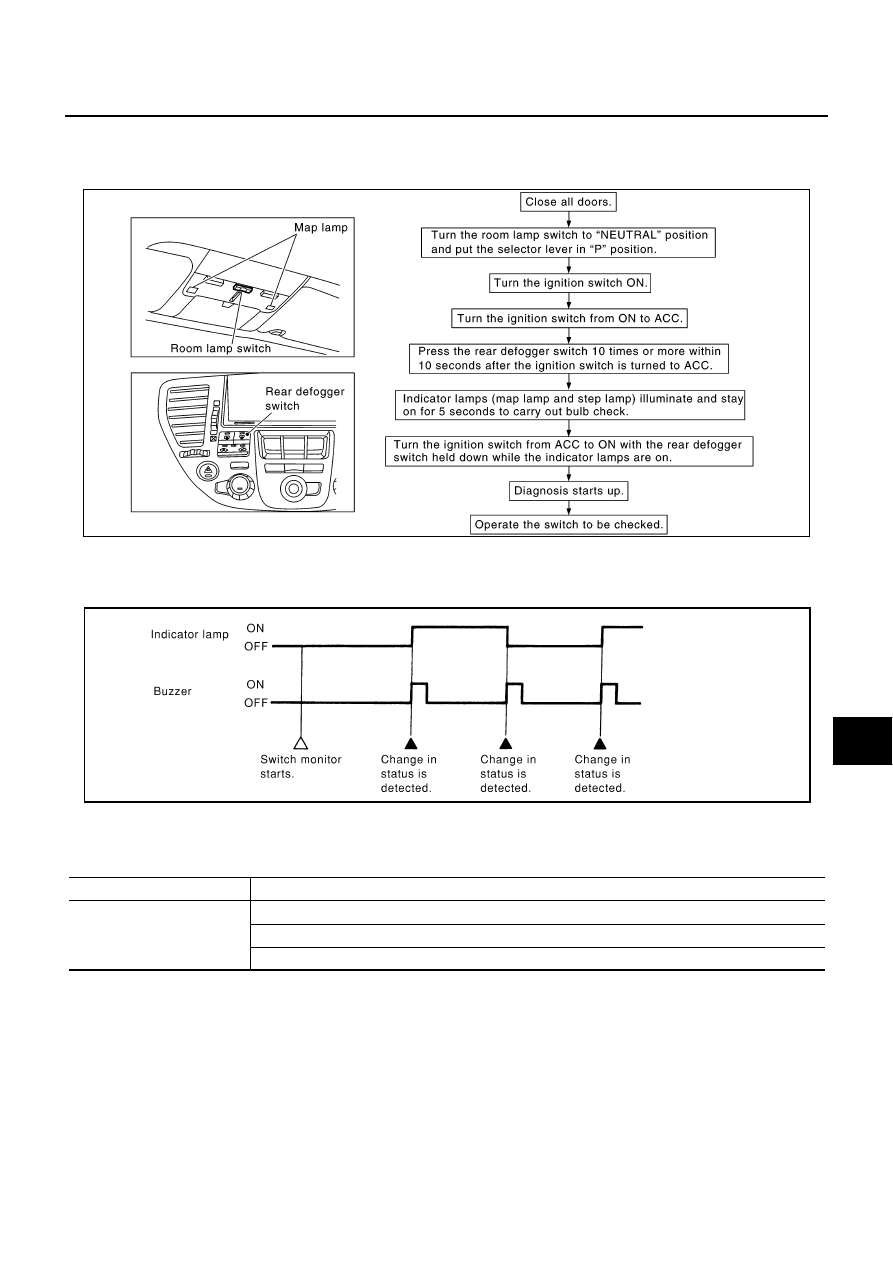
How to Perform Switch Monitor

Description

In this mode, when BCM detects the input signal from a switch in IVMS as shown below, the detection is
indicated by the map lamps and front step lamps with buzzer.

Switch Monitor Item

The status of the switch (except the ignition switch, interior lamp ill switch, and map lamp switch) as input
to each control unit can be monitored.

Cancel of Switch Monitor

If the following conditions are satisfied, the communication diagnosis is cancelled.

Turn ignition switch OFF.

Drive the vehicle more than 7 km/h (4 MPH).

PKIA7882E

PIIA0177E

Control unit

Item

BCM

Lighting switch (AUTO, 1ST position)

Front door switch (Driver side)

Front door switch (Passenger side)

LT-24

HEADLAMP (FOR USA)

Symptom Chart 1

AKS002F6

HEADLAMP SYSTEM

Symptom Chart 2

AKS003ZN

AUTO LIGHT SYSTEM

Symptom

Possible cause and reference

Neither headlamp operates.

Refer to 

LT-25, "Power Supply and Ground Circuit Inspection"

 .

Refer to 

LT-31, "Lighting Switch Circuit Inspection"

 .

If above systems are normal, replace the headlamp battery saver 
control unit.

Headlamp (low beam) does not operate, but headlamp (high 
beam) does operate.

Refer to 

LT-25, "Power Supply and Ground Circuit Inspection"

 .

Refer to 

LT-26, "Headlamp Relay-1 Circuit Inspection"

 .

If above systems are normal, replace the headlamp battery saver 
control unit.

Headlamp (high beam) does not operate, but headlamp (low 
beam) does operate.

Refer to 

LT-25, "Power Supply and Ground Circuit Inspection"

 .

Refer to 

LT-27, "Headlamp Relay-2 Circuit Inspection"

 .

If above systems are normal, replace the headlamp battery saver 
control unit.

RH low beam does not operate, but LH low beam does operate.

Refer to 

LT-25, "Power Supply and Ground Circuit Inspection"

 .

Refer to 

LT-26, "Headlamp Relay-1 Circuit Inspection"

 .

Refer to 

LT-28, "Headlamp (Low) Circuit Inspection"

 .

LH low beam does not operate, but RH low beam does operate.

RH high beam does not operate, but LH high beam does operate.

Refer to 

LT-29, "Headlamp (High) Circuit Inspection"

 .

Refer to 

LT-31, "Lighting Switch Circuit Inspection"

 .

LH high beam does not operate, but RH high beam does operate.

High beam indicator does not work.

Refer to 

LT-31, "High Beam Indicator Circuit Inspection"

 .

If above systems are normal, replace the combination meter.

Battery saver control does not operate properly.

Refer to 

LT-33, "Front Door Switch Circuit Inspection"

 .

Refer to 

LT-34, "Headlamp Battery Saver Control Unit Circuit 

Inspection"

 .

Refer to 

LT-31, "Lighting Switch Circuit Inspection"

 .

If above systems are normal, replace the headlamp battery saver 
control unit.

Symptom

Possible cause and reference

Parking (clearance) lamps and headlamps will not illuminate 
when outside of the vehicle becomes dark. (Lighting switch 1st 
position and 2nd position operate normally.)

Parking (clearance) lamps and headlamp will not go out when 
outside of the vehicle becomes light. (Lighting switch 1st position 
and 2nd position operate normally.)

Refer to 

LT-35, "Lighting Switch (AUTO) System Inspection"

 .

Refer to 

LT-36, "Optical Sensor System Inspection"

 .

If above systems are normal, replace the BCM.

Parking (clearance) lamps illuminate when outside of the vehicle 
becomes dark, but headlamp stay off. (Lighting switch 1st position 
and 2nd position operate normally.)

Refer to 

LT-38, "Headlamp Relay System Inspection"

 .

Refer to 

LT-36, "Optical Sensor System Inspection"

 .

If above systems are normal, replace the BCM.

Headlamps illuminate when outside of the vehicle becomes 
dark, but clearance lamps stay off. (Lighting switch 1st position 
and 2nd position operate normally.)

Headlamps go out when outside of the vehicle becomes light, 
but parking (clearance) lamps stay on.

Refer to 

LT-38, "Tail Lamp Relay System Inspection"

 .

If above system is normal, replace the BCM.

HEADLAMP (FOR USA)

LT-25

C

D

E

F

G

H

I

J

L

M

A

B

LT

Power Supply and Ground Circuit Inspection

AKS003RY

1. 

CHECK FUSE

Check if the headlamp battery saver control unit, headlamp relay-1 and -2 fuses are blown.

Refer to 

LT-11, "Wiring Diagram — H/LAMP —"

 .

OK or NG

OK

>> GO TO 2.

NG

>> If fuse is blown, be sure to eliminate cause of malfunction before installing new fuse.

2. 

CHECK HEADLAMP BATTERY SAVER CONTROL UNIT POWER SUPPLY CIRCUIT

1.

Turn ignition switch OFF.

2.

Disconnect headlamp battery saver control unit connector.

3.

Check voltage between headlamp battery saver control unit har-
ness connector M34 terminal 7 (Y/G) and ground.

OK or NG

OK

>> GO TO 3.

NG

>> Check harness for open or short between headlamp

battery saver control unit and fuse.

3. 

CHECK HEADLAMP RELAY-1 POWER SUPPLY CIRCUIT

1.

Remove headlamp relay-1.

2.

Check voltage between headlamp relay-1 harness connector
E3-4 terminals 2, 3 or 7 and ground.

OK or NG

OK

>> GO TO 4.

NG

>> Replace fuse, fusible link and relay block (J/B).

Unit or relay

Power source

Fuse No.

Headlamp battery saver control unit

Battery

6

Headlamp relay-1

Battery

55

57

Headlamp relay-2

Battery

73

7 (Y/G) - Ground

: Battery voltage should exist.

PKIA5841E

Terminals

Ignition switch position

(+)

(-)

OFF

Connector

Terminal

E3 - 4

2

Ground

Battery voltage

3

7

PKIA5842E

LT-26

HEADLAMP (FOR USA)

4. 

CHECK HEADLAMP RELAY-2 POWER SUPPLY CIRCUIT

1.

Remove headlamp relay-2.

2.

Check voltage between headlamp relay-2 harness connector E5
terminal 1 (PU) and ground.

3.

Check voltage between headlamp relay-2 harness connector E5
terminal 3 (PU) and ground.

OK or NG

OK

>> GO TO 5.

NG

>> Check harness for open or short between headlamp relay-2 and fuse.

5. 

CHECK HEADLAMP BATTERY SAVER CONTROL UNIT GROUND CIRCUIT

Check continuity between headlamp battery saver control unit har-
ness connector terminals and ground.

OK or NG

OK

>> INSPECTION END

NG

>> Check harness.

Headlamp Relay-1 Circuit Inspection

AKS003S0

1. 

CHECK HEADLAMP RELAY-1

1.

Turn ignition switch OFF.

2.

Remove headlamp relay-1.

3.

Apply 12V between headlamp relay-1 terminals 2 and 1, and
check continuity between terminals 3 and 5 and between 6 and
7.

OK or NG

OK

>> GO TO 2.

NG

>> Replace headlamp relay-1.

1 (PU) - Ground

: Battery voltage should exist.

3 (PU) - Ground

: Battery voltage should exist.

PKIA5843E

Terminals

Continuity

Connector

Terminal (Wire color)

M33

4 (B)

Ground

Yes

M34

11 (B) 

PKIA5844E

3 - 5

: Continuity should exist.

6 - 7

: Continuity should exist.

PKIA5845E


Content   ..  627  628  629  630   ..