Infiniti M45 (Y34). Manual - part 628
HEADLAMP (FOR USA)
LT-19
C
D
E
F
G
H
I
J
L
M
A
B
LT
Preliminary Check
AKS002F3
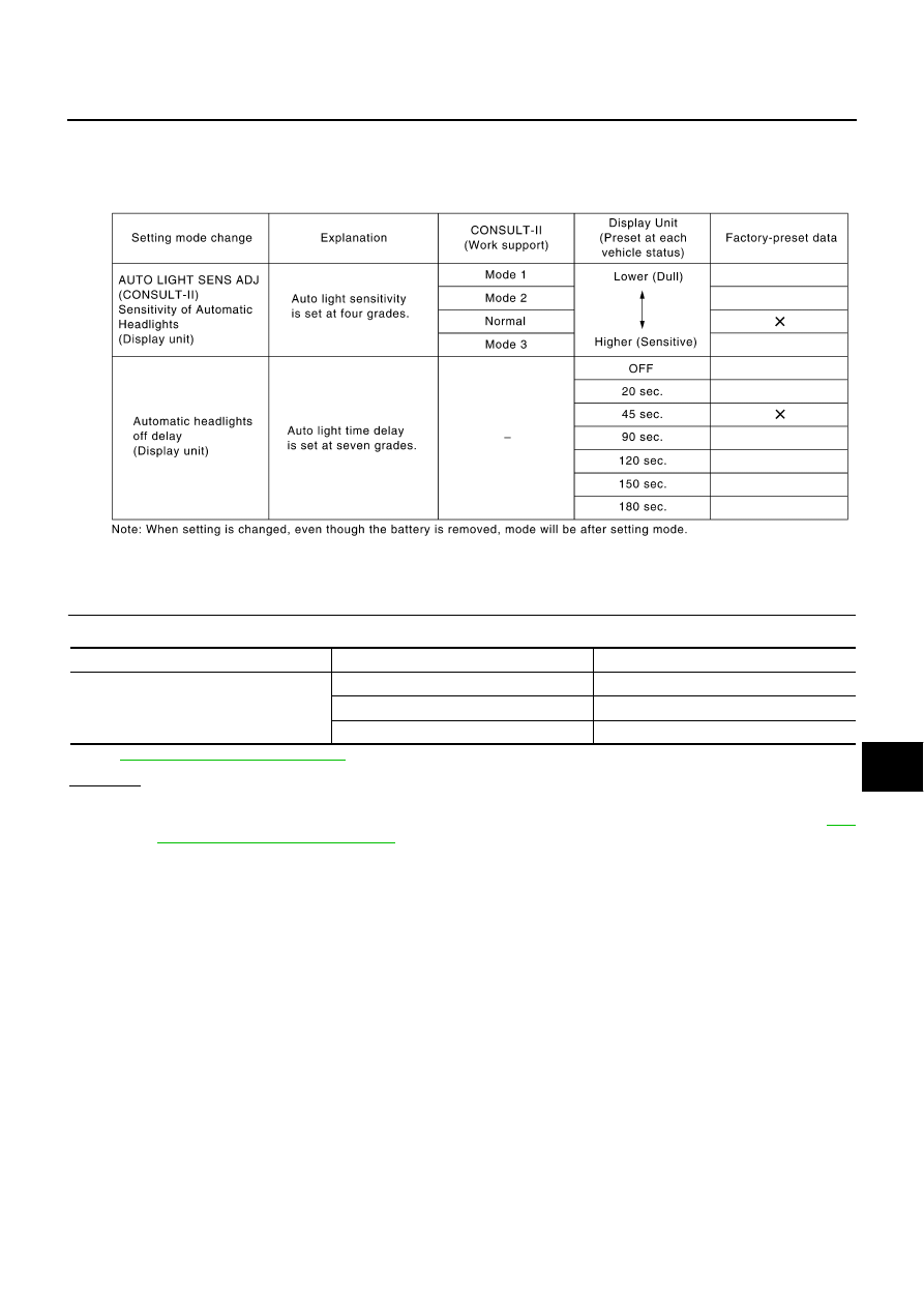
SETTING CHANGE FUNCTION FOR AUTO LIGHT SYSTEM
●
Setting for each operation can be changed using CONSULT-II and a display unit.
INSPECTION FOR POWER SUPPLY AND GROUND CIRCUIT
1.
CHECK FUSE
Check if any of the following fuses in BCM are blown.
Refer to
LT-11, "Wiring Diagram — H/LAMP —"
.
OK or NG
OK
>> GO TO 2.
NG
>> If fuse is blown, be sure to eliminate cause of malfunction before installing new fuse. Refer to
SKIA3782E
Unit
Power source
Fuse No.
BCM
Battery
3
Ignition switch ACC or ON position
21
Ignition switch ON or START position
1