Infiniti M45 (Y34). Manual - part 621
CAN SYSTEM (TYPE 2)
LAN-51
[CAN]
C
D
E
F
G
H
I
J
L
M
A
B
LAN
Circuit Check Between ICC Unit and Data Link Connector
AKS003YM
1.
CHECK CONNECTOR
1.
Turn ignition switch OFF.
2.
Check following terminals and connector for damage, bend and loose connection (connector side and
harness side).
–
Harness connector B211
–
Harness connector M141
OK or NG
OK
>> GO TO 2.
NG
>> Repair terminal or connector.
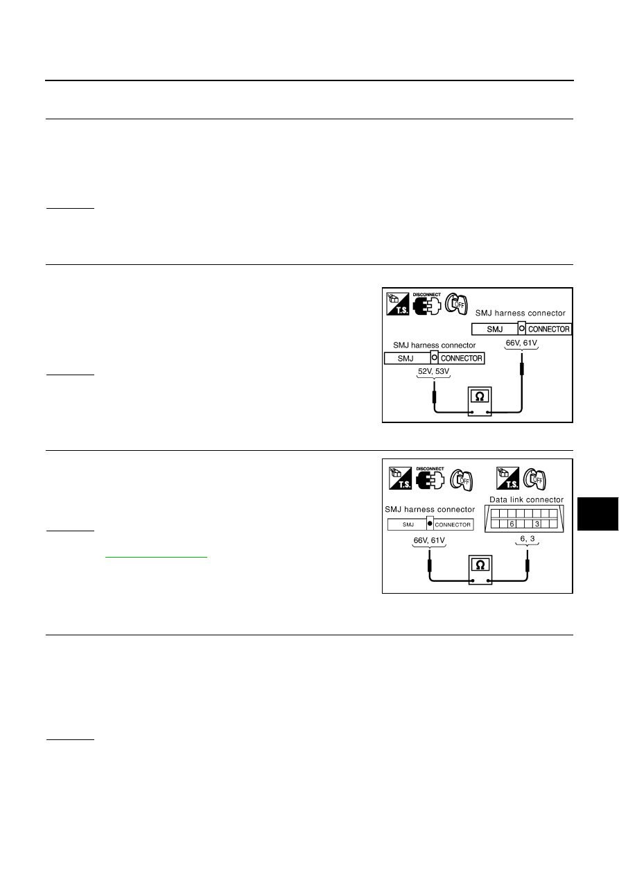
2.
CHECK HARNESS FOR OPEN CIRCUIT
1.
Disconnect harness connector B211.
2.
Check continuity between harness connector B211 terminals
52V (L), 53V (R) and harness connector B211 terminals 66V (L),
61V (R).
OK or NG
OK
>> GO TO 3.
NG
>> Repair harness.
3.
CHECK HARNESS FOR OPEN CIRCUIT
Check continuity between harness connector M141 terminals 66V
(L), 61V (R) and data link connector M31 terminals 6 (L), 3 (R).
OK or NG
OK
>> Connect all the connectors and diagnose again. Refer to
NG
>> Repair harness.
ECM Circuit Check
AKS003YE
1.
CHECK CONNECTOR
1.
Turn ignition switch OFF.
2.
Check following terminals and connector for damage, bend and loose connection (control module side
and harness side).
–
ECM connector
–
Harness connector F105
–
Harness connector M135
OK or NG
OK
>> GO TO 2.
NG
>> Repair terminal or connector.
52V (L) – 66V (L)
: Continuity should exist.
53V (R) – 61V (R)
: Continuity should exist.
SKIA3883E
66V (L) – 6 (L)
: Continuity should exist.
61V (R) – 3 (R)
: Continuity should exist.
SKIA3884E