Infiniti M45 (Y34). Manual - part 532


  Index      Infiniti     Infiniti M45 (Y34) - service repair manual 2004 year


Search            copyright infringement  


Content   ..  530  531  532  533   ..


Infiniti M45 (Y34). Manual - part 532


CYLINDER HEAD

EM-65

C

D

E

F

G

H

I

J

K

L

M

A

EM

CYLINDER HEAD

PFP:11041

On-Vehicle Service

ABS000LW

CHECKING COMPRESSION PRESSURE

1.

Warm up engine thoroughly. Then, stop it.

2.

Remove engine cover (with power tool). Refer to 

EM-12, "Removal and Installation"

 .

3.

Release fuel pressure.

a.

Remove fuel pump fuse, and start engine. Refer to 

EC-46, "FUEL PRESSURE RELEASE"

  for fuel pump

fuse location.

b.

After engine stalls, crank it two or three times to release all fuel pressure.

Let fuel pump fuse removed until the end of step 7.

4.

Remove ignition coil and spark plug from each cylinder. Refer to

EM-28, "Removal and Installation"

  and

EM-29, "Removal and Installation"

 .

5.

Connect engine tachometer (not required in use of CONSULT-II).
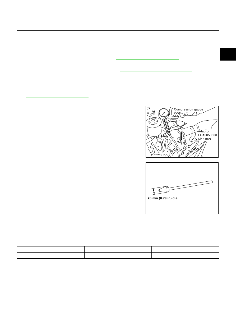
6.

Install compression gauge with adapter (SST or commercial ser-
vice tool) onto spark plug hole.

Use compression gauge adapter (SST) which is required on
No. 7 and No. 8 cylinders.

Use the compression gauge adapter (if SST is not used)
which picking up end inserted to spark plug hole is smaller
than 20 mm (0.79 in) in diameter. Otherwise, it may be caught
by cylinder head during removal.

7.

With accelerator pedal fully depressed, turn ignition switch to “START” for cranking. When the gauge
pointer stabilizes, read the compression pressure and engine rpm. Perform these steps to check each cyl-
inder.

Compression pressure

Unit: kPa (kg/cm

2

 , psi) /rpm

CAUTION:

Always use a fully charged battery to obtain specified engine speed.

If the engine speed is out of specified range, check battery liquid for proper gravity. Check engine
speed again with normal battery gravity. 

If compression pressure is below minimum value, check valve clearances and parts associated with
combustion chamber (Valve, valve seat, piston, piston ring, cylinder bore, cylinder head, cylinder head
gasket). After the checking, measure compression pressure again.

If some cylinders have low compression pressure, pour small amount of engine oil into the spark plug
hole of the cylinder to re-check it for compression.

PBIC1003E

SBIA0533E

Standard

Minimum

Difference limit between cylinders

  1,320 (13.5, 191) / 300

  1,130 (11.5, 164) / 300

      98 (1.0, 14) / 300

EM-66

CYLINDER HEAD

If the added engine oil improves the compression, the piston rings may be worn out or damaged. Check
the piston rings and replace if necessary.

If the compression pressure remains at low level despite the addition of engine oil, the valves may be
malfunctioning. Check the valves for damage. Replace the valve or valve seat accordingly.

If two adjacent cylinders have respectively low compression pressure and their compression remains
low even after the addition of engine oil, the gaskets are leaking. In such a case, replace the cylinder
head gaskets.

8.

Install removed parts in the reverse order of removal.

9.

Start engine, and confirm that engine runs smoothly.

10. Perform trouble diagnosis. If DTC appears, erase it. Refer to 

EC-73, "TROUBLE DIAGNOSIS"

 .

Removal and Installation

ABS000LX

REMOVAL

1.

Remove engine assembly from vehicle. Refer to 

EM-76, "Removal and Installation"

 .

2.

Remove the following components and related parts:

Auto tensioner of drive belts and idler pulley. Refer to 

EM-15, "Drive Belt Auto Tensioner and Idler Pul-

ley"

 .

Thermostat housing and hose. Refer to 

CO-24, "Removal and Installation"

 .

Oil pan and oil strainer. Refer to 

EM-25, "Removal and Installation"

 . 

Intake manifold upper and intake manifold lower. Refer to 

EM-18, "Removal and Installation"

 . 

Fuel damper and fuel hose assembly, fuel tube (right and left) and fuel injector. Refer to 

EM-31,

"Removal and Installation"

 . 

Ignition coil. Refer to 

EM-28, "Removal and Installation"

 .

Rocker cover. Refer to 

EM-36, "Removal and Installation"

 .

3.

Remove crankshaft pulley, front cover, oil pump, and timing chain. Refer to 

EM-38, "Removal and Installa-

tion"

 .

4.

Remove camshaft sprockets and camshafts. Refer to 

EM-49, "Removal and Installation"

 .

1.

Engine coolant temperature sensor

2.

Washer

3.

Cylinder head gasket (left bank)

4.

Harness bracket

5.

Cylinder head (right bank)

6.

Cylinder head bolt

7.

Cylinder head gasket (right bank)

8.

Cylinder head bolt

9.

Cylinder head (left bank)

PBIC2407E

CYLINDER HEAD

EM-67

C

D

E

F

G

H

I

J

K

L

M

A

EM

5.

Remove cylinder head loosening bolts in reverse order shown in
the figure and using the cylinder head bolt wrench (commercial
service tool).

6.

Remove cylinder head gaskets.

INSPECTION AFTER REMOVAL
Outer Diameter of Cylinder Head Bolts

Cylinder head bolts are tightened by plastic zone tightening
method. Whenever the size difference between d1 and d2
exceeds the limit, replace them with new one. 

If reduction of outer diameter appears in a position other than
d2, use it as d2 point.

CYLINDER HEAD DISTORTION

NOTE:
When performing this inspection, cylinder block distortion should be also checked. Refer to 

EM-99, "CYLIN-

DER BLOCK DISTORTION"

 .

1.

Wipe off oil and remove water scale (like deposit), gasket,
sealer, carbon, etc. with scraper.

CAUTION:

Use utmost care not to allow gasket debris to enter pas-
sages for oil or water.

2.

At each of several locations on bottom surface of cylinder head,
measure distortion in six directions.

If it exceeds the limit, replace cylinder head.

INSTALLATION

1.

Install cylinder head gasket.

2.

Follow the steps below to tighten fixing bolts in the numerical
order shown in figure to install cylinder head.

CAUTION:

If cylinder head bolts are re-used, check their outer diam-
eters before installation. Refer to 

EM-67, "Outer Diameter

of Cylinder Head Bolts"

 .

In step “c”, loosen bolts in reverse order of that indicated
in figure.

a.

Apply engine oil to threads and seating surface of bolts.

b.

Tighten all bolts.

PBIC0068E

Limit (d1 - d2)

: More than 0.18 mm (0.0071 in)

KBIA0189E

Limit

: 0.1mm (0.004 in)

PBIC0075E

 : 98.1 N·m (10 kg-m, 72 ft-lb)

PBIC0068E

EM-68

CYLINDER HEAD

c.

Completely loosen all bolts.

d.

Tighten all bolts.

e.

Turn all bolts 60 degrees clockwise. (Angle tightening)

f.

Turn all bolts 60 degrees clockwise again. (Angle tightening)

CAUTION:

Check and confirm the tightening angle by using the angle
wrench (SST) and the cylinder head bolt wrench (commer-
cial service tool). Avoid judgment by visual inspection with-
out the SST.

3.

Install in the reverse order of removal. 

Disassembly and Assembly

ABS000LY

CAUTION:

Attach tags to valve lifters so as not to mix them up.

 : 0 N·m (0 kg-m, 0 ft-lb)

 : 44.1 N·m (4.5 kg-m, 33 ft-lb)

PBIC0069E

1.

Spark plug

2.

Adjusting shim

3.

Valve lifter

4.

Valve collet

5.

Valve spring retainer

6.

Valve spring (with valve spring seat)

7.

Valve oil seal

8.

Valve guide

9.

Valve seat

10.

Valve (INT)

11.

Valve (EXH)

12.

Cylinder head (left bank)

13.

Spark plug tube

14.

Cylinder head (right bank)

PBIC2133E


Content   ..  530  531  532  533   ..