Infiniti M45 (Y34). Manual - part 529


  Index      Infiniti     Infiniti M45 (Y34) - service repair manual 2004 year


Search            copyright infringement  


Content   ..  527  528  529  530   ..


Infiniti M45 (Y34). Manual - part 529


CAMSHAFT

EM-53

C

D

E

F

G

H

I

J

K

L

M

A

EM

Valve Lifter Clearance

Outer Diameter of Valve Lifter

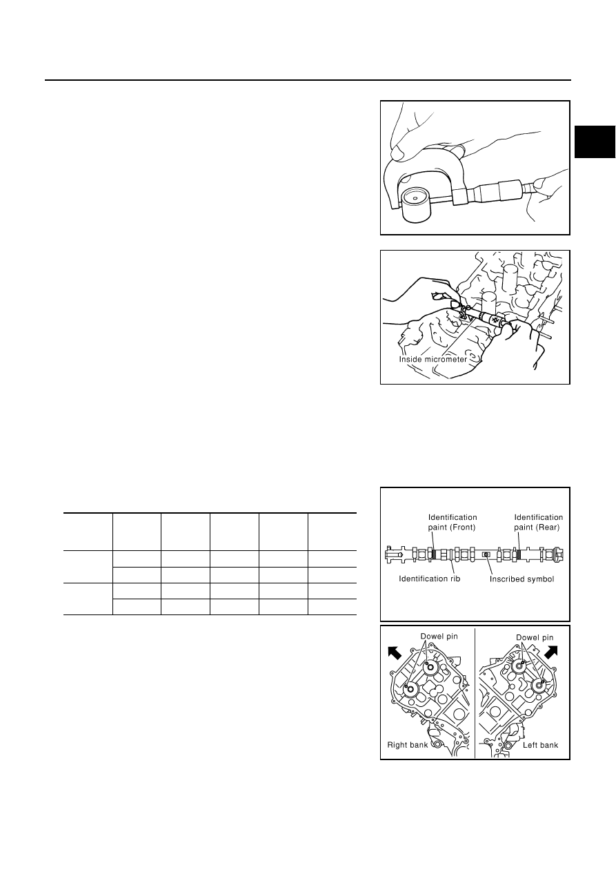
Measure outer diameter of valve lifter with micrometer.

Valve Lifter Hole Diameter

Using inside micrometer, measure diameter of valve lifter hole of
cylinder head.

Calculation of Valve Lifter Clearance

(Valve lifter clearance) = (hole diameter of valve lifter) – (outer
diameter of valve lifter)

If out of the standard, referring to each specification of outer and inner diameter, replace either or both
valve lifter and cylinder head.

INSTALLATION

1.

Install valve lifters and adjusting shims if removed.

Install removed parts in the same locations as before.

2.

Install camshafts. Refer to the table below for identification of
right and left bank, and intake and exhaust.

Install so that dowel pin at the front of camshaft face is in the
direction shown in the figure. (No. 1 cylinder at compression
TDC)

NOTE:
Though camshaft does not stop at the position as shown in
the figure, for the placement of cam nose, it is generally
accepted camshaft is placed for the same direction of the fig-
ure.

Standard: 33.965 - 33.975 mm (1.3372 - 1.3376 in)

SEM961E

Standard:

34.000 - 34.016 mm (1.3386 - 1.3392 in)

Standard:

0.025 - 0.051 mm (0.0010 - 0.0020 in)

PBIC0043E

Bank

INT/ EXH

Identifica-

tion paint 

(front)

Identifica-

tion paint 

(rear)

Identifica-

tion rib

Inscribed 

symbol

RH

INT

Blue

Yes.

RH

EXH

Orange

Yes.

RH

LH

INT

Blue

No.

LH

EXH

Orange

No.

LH

PBIC0032E

SBIA0366E

EM-54

CAMSHAFT

3.

Install camshaft brackets.

Remove foreign material completely from camshaft bracket
backside and from cylinder head installation face.

Install by referring to installation location mark on upper sur-
face and front mark.

Install so that installation location mark can be correctly read
when viewed from the side of left exhaust bank.

Apply liquid gasket to camshaft bracket (No.1) as in the illus-
tration.
Use Genuine RTV Silicone Sealant or equivalent. Refer to

GI-46, "RECOMMENDED CHEMICAL PRODUCTS AND
SEALANTS"

.

CAUTION:

After installation, be sure to wipe off any excessive liquid
gasket leaking from part “A” and “B”(both on right and
left sides).

Remove completely any excess of liquid gasket inside
bracket. 

Apply liquid gasket to camshaft bracket (No.6) on left bank
intake as in illustration.

CAUTION:

After installation, be sure to wipe off any excessive liquid
gasket leaking from part “A”, and “ B”(both on right and
left sides).

Remove completely any excess of liquid gasket inside
bracket. 

PBIC0034E

PBIC2356E

PBIC2357E

CAMSHAFT

EM-55

C

D

E

F

G

H

I

J

K

L

M

A

EM

4.

Tighten camshaft bracket bolts in the following steps, in numeri-
cal order as shown in the figure.

a.

Tighten No. 9 to 12 in numerical order as shown.

b.

Tighten No. 1 to 8 in numerical order as shown.

c.

Tighten No. 13 to 14 in numerical order as shown. (Left bank
only)

d.

Tighten all bolts in numerical order as shown.

e.

Tighten No. 1 to 12 in numerical order as shown.

f.

Tighten No. 13 to 14 in numerical order as shown. (Left bank
only)

CAUTION:

After tightening fixing bolts of camshaft brackets, be sure to wipe off excessive liquid gasket from
the parts listed below. 

Mating surface of rocker cover 

Mating surface of front cover

5.

Install camshaft sprockets.

Install by checking with identification mark on surface.

Install camshaft sprocket (EXH) by selectively using the
groove of dowel pin according to the bank. (Common part
used for both banks.)

Lock the hexagonal part of camshaft in the same way as for
removal, and tighten fixing bolts.

6.

Check and adjust valve clearances. Refer to 

EM-55, "Valve Clearance"

 .

7.

Install in the reverse order of removal.

Valve Clearance

ABS004RV

INSPECTION

Perform inspection as follows after removal, installation or replacement of camshaft or valve-related parts, or if
there is unusual engine conditions due to changes in valve clearance (engine starting, idling, and/or noise). 

1.

Warm up engine. Then stop it.

2.

Remove engine cover with power tool and air duct (inlet). Refer to 

EM-12, "Removal and Installation"

 .

3.

Remove rocker covers (right and left bank) with power tool. Refer to 

EM-36, "Removal and Installation"

 .

 : 1.96 N·m (0.2 kg-m, 1 ft-lb)

 : 1.96 N·m (0.2 kg-m, 1 ft-lb)

 : 1.96 N·m (0.2 kg-m, 1 ft-lb)

 : 5.88 N·m (0.6 kg-m, 4 ft-lb)

 : 10.41 N·m (1.1 kg-m, 8 ft-lb)

 : 31.35 N·m (3.2 kg-m, 23 ft-lb)

PBIC0031E

PBIC2345E

EM-56

CAMSHAFT

4.

Turn crankshaft pulley in normal direction (clockwise when
viewed from engine front) to align TDC identification notch (with-
out paint mark) with timing indicator.

5.

At this time, check that the both intake and exhaust cam noses
of No. 1 cylinder (top front on left bank) face outside.

If they do not face outside, turn crankshaft pulley by 360
degrees once more.

6.

By referring to the figure, measure valve clearances at locations
marked “X” as shown in the table below (locations indicated with
black arrow in figure) with feeler gauge.

NOTE:
Firing order 1-8-7-3-6-5-4-2

No.1 cylinder compression TDC

Use feeler gauge. 

*Reference data at approximately 20

°

C (68

°

F)

PBIC2341E

KBIA0400J

Measuring position (right bank)

No.2 CYL

No.4 CYL

No.6 CYL

No. 8 CYL

No. 1 cylinder at TDC

 EXH


×

INT

×

×


Measuring position (left bank)

No.1 CYL

No. 3 CYL

No. 5 CYL

No. 7 CYL

No. 1 cylinder at TDC

INT

×

×


EXH

×

×

PBIC0823E

Valve clearance standard:

Hot

Intake

: 0.304 - 0.416 mm (0.012 - 0.016 in)

Exhaust

: 0.308 - 0.432 mm (0.012 - 0.017 in)

Cold*

Intake

: 0.26 - 0.34 mm (0.010 - 0.013 in)

Exhaust

: 0.29 - 0.37 mm (0.011 - 0.015 in)

PBIC0046E


Content   ..  527  528  529  530   ..