Infiniti M45 (Y34). Manual - part 471
 

  Index      Infiniti     Infiniti M45 (Y34) - service repair manual 2004 year


Search            copyright infringement  


Content   ..  469  470  471  472   ..


Infiniti M45 (Y34). Manual - part 471


DTC P1456 EVAP CONTROL SYSTEM

EC-573

C

D

E

F

G

H

I

J

K

L

M

A

EC

21. 

CHECK REFUELING EVAP VAPOR LINE

Check refueling EVAP vapor line between EVAP canister and fuel tank for clogging, kink, looseness and
improper connection. For location, refer to 

EC-698, "ON BOARD REFUELING VAPOR RECOVERY (ORVR)"

.
OK or NG

OK

>> GO TO 22.

NG

>> Repair or replace hoses and tubes.

22. 

CHECK SIGNAL LINE AND RECIRCULATION LINE

Check signal line and recirculation line between filler neck tube and fuel tank for clogging, kink, cracks, loose-
ness and improper connection.
OK or NG

OK

>> GO TO 23.

NG

>> Repair or replace hoses, tubes or filler neck tube.

23. 

CHECK REFUELING CONTROL VALVE

Refer to 

EC-701, "Component Inspection"

 .

OK or NG

OK

>> GO TO 24.

NG

>> Replace refueling control valve with fuel tank. 

24. 

CHECK FUEL LEVEL SENSOR

Refer to 

DI-19, "CHECK FUEL LEVEL SENSOR UNIT"

 .

OK or NG

OK

>> GO TO 25.

NG

>> Replace fuel level sensor unit.

25. 

CHECK INTERMITTENT INCIDENT

Refer to 

EC-132, "TROUBLE DIAGNOSIS FOR INTERMITTENT INCIDENT"

 .

>> INSPECTION END

Component Inspection

ABS002VR

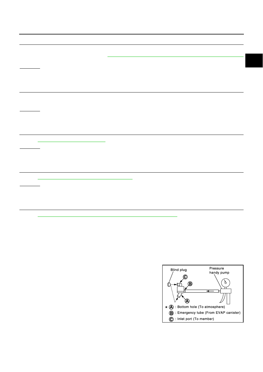
WATER SEPARATOR

1.

Check visually for insect nests in the water separator air inlet.

2.

Check visually for cracks or flaws in the appearance.

3.

Check visually for cracks or flaws in the hose.

4.

Check that A  and C  are not clogged by blowing air into B  with
A , and then C  plugged.

5.

In case of NG in items 2 - 4, replace the parts.

NOTE:

Do not disassemble water separator.

PBIB1032E

EC-574

DTC P1464 FUEL LEVEL SENSOR

DTC P1464 FUEL LEVEL SENSOR

PFP:25060

Component Description

ABS002R1

The fuel level sensor is mounted in the fuel level sensor unit. The
sensor detects a fuel level in the fuel tank and transmits a signal to
the ECM.
It consists of two parts, one is mechanical float and the other is vari-
able resistor. Fuel level sensor output voltage changes depending on
the movement of the fuel mechanical float.

On Board Diagnosis Logic

ABS002R2

ECM receives two signals from the fuel level sensor.
One is fuel level sensor power supply circuit, and the other is fuel level sensor ground circuit.
This diagnosis indicates the latter to detect open circuit malfunction.

DTC Confirmation Procedure

ABS002R3

NOTE:
If DTC Confirmation Procedure has been previously conducted, always turn ignition switch OFF and wait at
least 10 seconds before conducting the next test.

 WITH CONSULT-II

1.

Turn ignition switch ON.

2.

Select “DATA MONITOR” mode with CONSULT-II.

3.

Wait at least 5 seconds.

4.

If 1st trip DTC is detected, go to 

EC-576, "Diagnostic Procedure"

.

 WITH GST

Follow the procedure WITH CONSULT-II above.

PBIB1241E

DTC No.

Trouble diagnosis name

DTC detecting condition

Possible cause

P1464
1464

Fuel level sensor circuit 
ground signal

A high voltage from the sensor is sent to ECM.

Harness or connectors
(The sensor circuit is open or shorted)

SEF195Y

DTC P1464 FUEL LEVEL SENSOR

EC-575

C

D

E

F

G

H

I

J

K

L

M

A

EC

Wiring Diagram

ABS002R4

TBWA0295E

EC-576

DTC P1464 FUEL LEVEL SENSOR

Specification data are reference values and are measured between each terminal and ground.

CAUTION:

Do not use ECM ground terminals when measuring input/output voltage. Doing so may result in dam-
age to the ECM's transistor. Use a ground other than ECM terminals, such as the ground.

Diagnostic Procedure

ABS002R5

1. 

CHECK GROUND CONNECTIONS

1.

Turn ignition switch OFF.

2.

Loosen and retighten two ground screws. 
Refer to 

EC-141, "Ground Inspection"

 .

OK or NG

OK

>> GO TO 2.

NG

>> Repair or replace ground connections.

2. 

CHECK FUEL LEVEL SENSOR GROUND CIRCUIT FOR OPEN AND SHORT

1.

Disconnect ECM harness connector.

2.

Disconnect combination meter harness connector.

3.

Check harness continuity between ECM terminal 107 and combination meter terminal 31.
Refer to Wiring Diagram.

4.

Also check harness for short to power.

OK or NG

OK

>> GO TO 4.

NG

>> GO TO 3.

3. 

DETECT MALFUNCTIONING PART

Check the following.

Harness connectors F105, M135

Joint connector-15

Harness for open and short between ECM and combination meter.

>> Replace open circuit or short to ground or short to power in harness or connectors.

4. 

CHECK INTERMITTENT INCIDENT

Refer to 

EC-132, "TROUBLE DIAGNOSIS FOR INTERMITTENT INCIDENT"

 .

>> INSPECTION END

TER-

MINAL 

NO.

WIRE 

COLOR

ITEM

CONDITION

DATA (DC Voltage)

119

R/L

Fuel level sensor

[Ignition switch: ON]

Approximately 0 - 4.8V
Output voltage varies with fuel 
level.

107

B

Fuel level sensor ground

[Engine is running]

Idle speed

Approximately 0V

PBIB1118E

Continuity should exist.


Content   ..  469  470  471  472   ..