Infiniti M45 (Y34). Manual - part 453


  Index      Infiniti     Infiniti M45 (Y34) - service repair manual 2004 year


Search            copyright infringement  


Content   ..  451  452  453  454   ..


Infiniti M45 (Y34). Manual - part 453


DTC P1147, P1167 HO2S2

EC-501

C

D

E

F

G

H

I

J

K

L

M

A

EC

3. 

CHECK HO2S2 GROUND CIRCUIT FOR OPEN AND SHORT

1.

Turn ignition switch OFF.

2.

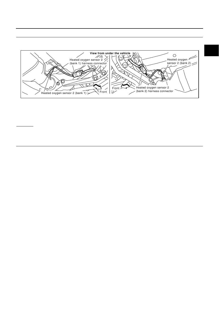
Disconnect heated oxygen sensor 2 harness connector.

3.

Check harness continuity between HO2S2 terminal 4 and ground.
Refer to Wiring Diagram.

4.

Also check harness for short to power.

OK or NG

OK

>> GO TO 5.

NG

>> GO TO 4.

4. 

DETECT MALFUNCTIONING PART

Check the following.

Harness connectors E315, F5

Joint connector-29

Harness open or short between HO2S2 and ground

>> Repair open circuit or short to power in harness or connectors.

Continuity should exist.

PBIB0018E

EC-502

DTC P1147, P1167 HO2S2

5. 

CHECK HO2S2 INPUT SIGNAL CIRCUIT FOR OPEN AND SHORT

1.

Disconnect ECM harness connector.

2.

Check harness continuity between ECM terminal and HO2S2 terminal as follows.
Refer to Wiring Diagram.

3.

Check harness continuity between the following terminals and ground.
Refer to Wiring Diagram.

4.

Also check harness for short to power.

OK or NG

OK

>> GO TO 7.

NG

>> GO TO 6.

6. 

DETECT MALFUNCTIONING PART

Check the following.

Harness connectors E315, F5

Harness open or short between HO2S2 and ECM

>> Repair open circuit or short to ground or short to power in harness or connectors.

7. 

CHECK HEATED OXYGEN SENSOR 2

Refer to 

EC-502, "Component Inspection"

 .

OK or NG

OK

>> GO TO 8.

NG

>> Replace malfunctioning heated oxygen sensor 2.

8. 

CHECK INTERMITTENT INCIDENT

Refer to 

EC-132, "TROUBLE DIAGNOSIS FOR INTERMITTENT INCIDENT"

 .

>> INSPECTION END

Component Inspection

ABS002P5

HEATED OXYGEN SENSOR 2

 With CONSULT-II

1.

Start engine and warm it up to the normal operating temperature.

2.

Turn ignition switch OFF and wait at least 10 seconds.

3.

Start engine and keep engine speed between 3,500 and 4,000 rpm for 1 minute under no load.

4.

Let engine idle for 1 minute.

DTC

Terminals

Bank

ECM

Sensor

P1147

123

1

1

P1167

124

1

2

Continuity should exist.

DTC

Terminals

Bank

ECM

Sensor

P1147

123

1

1

P1167

124

1

2

Continuity should not exist.

DTC P1147, P1167 HO2S2

EC-503

C

D

E

F

G

H

I

J

K

L

M

A

EC

5.

Select “FUEL INJECTION” in “ACTIVE TEST” mode, and select
“HO2S2 (B1)/(B2)” as the monitor item with CONSULT-II.

6.

Check “HO2S2 (B1)/(B2)” at idle speed when adjusting “FUEL INJECTION” to 

±

25%.

“HO2S2 (B1)/(B2)” should be above 0.58V at least once when the “FUEL INJECTION” is +25%.
“HO2S2 (B1)/(B2)” should be below 0.48V at least once when the “FUEL INJECTION” is 

25%.

CAUTION:

Discard any heated oxygen sensor which has been dropped from a height of more than 0.5 m (19.7
in) onto a hard surface such as a concrete floor; use a new one.

Before installing new oxygen sensor, clean exhaust system threads using Oxygen Sensor Thread
Cleaner tool J-43897-18 or J-43897-12 and approved anti-seize lubricant.

 Without CONSULT-II

1.

Start engine and warm it up to the normal operating temperature.

2.

Turn ignition switch OFF and wait at least 10 seconds.

3.

Start engine and keep engine speed between 3,500 and 4,000 rpm for 1 minute under no load.

4.

Let engine idle for 1 minute.

5.

Set voltmeter probes between ECM terminal 123 [HO2S2 (B1) signal] or 124 [HO2S2 (B2) signal] and
ground.

6.

Check the voltage when revving up to 4,000 rpm under no load
at least 10 times.
(Depress and release accelerator pedal as soon as possible.)
The voltage should be above 0.58V at least once during this
procedure.
If the voltage is above 0.58V at step 6, step 7 is not neces-
sary.

7.

Keep vehicle at idling for 10 minutes, then check voltage. Or
check the voltage when coasting from 80 km/h (50 MPH) in D
position.
The voltage should be below 0.48V at least once during this
procedure.

8.

If NG, replace heated oxygen sensor 2.

CAUTION:

Discard any heated oxygen sensor which has been dropped from a height of more than 0.5 m (19.7
in) onto a hard surface such as a concrete floor; use a new one.

Before installing new oxygen sensor, clean exhaust system threads using Oxygen Sensor Thread
Cleaner tool J-43897-18 or J-43897-12 and approved anti-seize lubricant.

PBIB1918E

PBIB1153E

PBIB2079E

EC-504

DTC P1147, P1167 HO2S2

Removal and Installation

ABS002P6

HEATED OXYGEN SENSOR 2

Refer to 

EM-22, "EXHAUST MANIFOLD AND THREE WAY CATALYST"

 .


Content   ..  451  452  453  454   ..