Infiniti M45 (Y34). Manual - part 434
DTC P1102 MAF SENSOR
EC-425
C
D
E
F
G
H
I
J
K
L
M
A
EC
Specification data are reference values and are measured between each terminal and ground.
CAUTION:
Do not use ECM ground terminals when measuring input/output voltage. Doing so may result in dam-
age to the ECM's transistor. Use a ground other than ECM terminals, such as the ground.
Diagnostic Procedure
ABS002MS
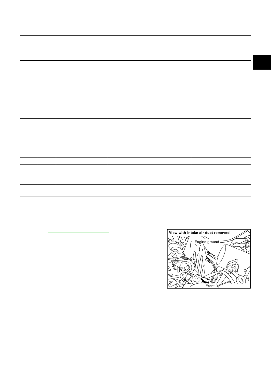
1.
CHECK GROUND CONNECTIONS
1.
Turn ignition switch OFF.
2.
Loosen and retighten two ground screws.
Refer to
OK or NG
OK
>> GO TO 2.
NG
>> Repair or replace ground connections.
TER-
MINAL
NO.
WIRE
COLOR
ITEM
CONDITION
DATA (DC Voltage)
42
W/B
ECM relay
(Self shut-off)
[Engine is running]
[Ignition switch: OFF]
●
A few seconds after turning ignition switch
OFF
0 - 1.0V
[Ignition switch: OFF]
●
More than a few seconds after turning igni-
tion switch OFF
BATTERY VOLTAGE
(11 - 14V)
91
B/Y
Mass air flow sensor
[Engine is running]
●
Warm-up condition
●
Idle speed
1.1 - 1.5V
[Engine is running]
●
Warm-up condition
●
Engine speed: 2,500 rpm.
1.7 - 2.4V
103
L
Sensor power supply
[Ignition switch: ON]
Approximately 5V
109
LG
Mass air flow sensor ground
[Engine is running]
●
Warm-up condition
●
Idle speed
Approximately 0V
163
166
R
R
Power supply for ECM
[Ignition switch: ON]
BATTERY VOLTAGE
(11 - 14V)
PBIB1118E