Infiniti M45 (Y34). Manual - part 404
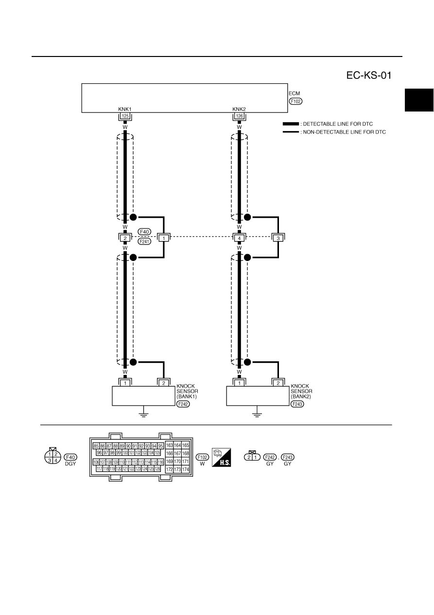
DTC P0327, P0328, P0332, P0333 KS
EC-305
C
D
E
F
G
H
I
J
K
L
M
A
EC
Wiring Diagram
ABS002JC
TBWM0021E
|
|
|
DTC P0327, P0328, P0332, P0333 KS EC-305 C D E F G H I J K L M A EC Wiring Diagram ABS002JC TBWM0021E |