Infiniti M45 (Y34). Manual - part 379


  Index      Infiniti     Infiniti M45 (Y34) - service repair manual 2004 year


Search            copyright infringement  


Content   ..  377  378  379  380   ..


Infiniti M45 (Y34). Manual - part 379


DTC P0125 ECT SENSOR

EC-205

C

D

E

F

G

H

I

J

K

L

M

A

EC

DTC P0125 ECT SENSOR

PFP:22630

Component Description

ABS002G3

NOTE:
If DTC P0125 is displayed with P0117 or P0118, first perform the trouble diagnosis for DTC P0117 or
P0118. Refer to 

EC-193, "DTC P0117, P0118 ECT SENSOR"

 .

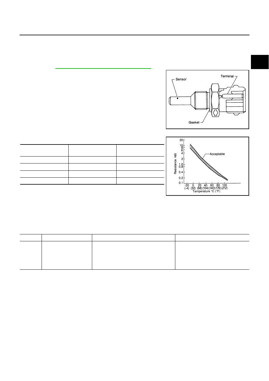
The engine coolant temperature sensor is used to detect the engine
coolant temperature. The sensor modifies a voltage signal from the
ECM. The modified signal returns to the ECM as the engine coolant
temperature input. The sensor uses a thermistor which is sensitive to
the change in temperature. The electrical resistance of the ther-
mistor decreases as temperature increases.

<Reference data>

*: This data is reference values and is measured between ECM terminal 121 (Engine
coolant temperature sensor) and ground.

CAUTION:

Do not use ECM ground terminals when measuring input/output voltage. Doing so may result in dam-
age to the ECM's transistor. Use a ground other than ECM terminals, such as the ground.

On Board Diagnosis Logic

ABS002G4

This self-diagnosis has the one trip detection logic.

SEF594K

Engine coolant 

temperature

°

C (

°

F)

Voltage*

V

Resistance

k

–10 (14)

4.4

7.0 - 11.4

20 (68)

3.5

2.1 - 2.9

50 (122)

2.2

0.68 - 1.00

90 (194)

0.9

0.236 - 0.260

SEF012P

DTC No.

Trouble diagnosis name

DTC detecting condition

Possible cause

P0125
0125

Insufficient engine coolant 
temperature for closed loop 
fuel control

Voltage sent to ECM from the sensor is not 
practical, even when some time has passed 
after starting the engine.

Engine coolant temperature is insufficient for 
closed loop fuel control.

Harness or connectors
(High resistance in the circuit)

Engine coolant temperature sensor

Thermostat

EC-206

DTC P0125 ECT SENSOR

DTC Confirmation Procedure

ABS002G5

CAUTION:

Be careful not to overheat engine.
NOTE:
If DTC Confirmation Procedure has been previously conducted, always turn ignition switch OFF and wait at
least 10 seconds before conducting the next test.

 WITH CONSULT-II

1.

Turn ignition switch ON.

2.

Select “DATA MONITOR” mode with CONSULT-II.

3.

Check that “COOLAN TEMP/S” is above 10

°

C (50

°

F).

If it is above 10

°

C (50

°

F), the test result will be OK.

If it is below 10

°

C (50

°

F), go to following step.

4.

Start engine and run it for 65 minutes at idle speed.
If “COOLAN TEMP/S” increases to more than 10

°

C (50

°

F)

within 65 minutes, stop engine because the test result will
be OK.

5.

If DTC is detected, go to 

EC-206, "Diagnostic Procedure"

 .

 WITH GST

Follow the procedure “WITH CONSULT-II” above.

Diagnostic Procedure

ABS002G7

1. 

CHECK GROUND CONNECTIONS

1.

Turn ignition switch OFF.

2.

Loosen and retighten two ground screws. 
Refer to 

EC-141, "Ground Inspection"

 .

OK or NG

OK

>> GO TO 2.

NG

>> Repair or replace ground connections.

2. 

CHECK ENGINE COOLANT TEMPERATURE SENSOR

Refer to 

EC-207, "Component Inspection"

 .

OK or NG

OK

>> GO TO 3.

NG

>> Replace engine coolant temperature sensor.

SEF174Y

PBIB1118E

DTC P0125 ECT SENSOR

EC-207

C

D

E

F

G

H

I

J

K

L

M

A

EC

3. 

CHECK THERMOSTAT OPERATION

When the engine is under cold [lower than 70

°

C (158

°

F)] condition, grasp lower radiator hose and confirm the

engine coolant does not flow.

OK or NG

OK

>> GO TO 4.

NG

>> Repair or replace thermostat. Refer to 

CO-24, "THERMOSTAT AND WATER CONTROL VALVE"

 .

4. 

CHECK INTERMITTENT INCIDENT

Refer to 

EC-132, "TROUBLE DIAGNOSIS FOR INTERMITTENT INCIDENT"

 .

Refer to 

EC-195, "Wiring Diagram"

 .

>> INSPECTION END

Component Inspection

ABS002G8

ENGINE COOLANT TEMPERATURE SENSOR

1.

Check resistance between engine coolant temperature sensor
terminals 1 and 2 as shown in the figure.

<Reference data>

2.

If NG, replace engine coolant temperature sensor.

Removal and Installation

ABS002G9

ENGINE COOLANT TEMPERATURE SENSOR

Refer to 

EM-65, "CYLINDER HEAD"

 .

PBIB2005E

Engine coolant temperature

°

C (

°

F)

Resistance

k

10 (14)

7.0 - 11.4

20 (68)

2.1 - 2.9

50 (122)

0.68 - 1.00

90 (194)

0.236 - 0.260

SEF012P

EC-208

DTC P0127 IAT SENSOR

DTC P0127 IAT SENSOR

PFP:22630

Component Description

ABS002GA

The intake air temperature sensor is built into mass air flow sensor.
The sensor detects intake air temperature and transmits a signal to
the ECM.
The temperature sensing unit uses a thermistor which is sensitive to
the change in temperature. Electrical resistance of the thermistor
decreases in response to the temperature rise.

<Reference data>

*: This data is reference values and is measured between ECM terminal 99 (Intake
air temperature sensor) and ground.

CAUTION:

Do not use ECM ground terminals when measuring input/output
voltage. Doing so may result in damage to the ECM's transistor. Use a ground other than ECM termi-
nals, such as the ground.

On Board Diagnosis Logic

ABS002GB

SEC266C

Intake air 

temperature

°

C (

°

F)

Voltage*

V

Resistance

k

10 (14)

4.43

7.9 - 9.3

25 (77)

3.32

1.9 - 2.1

80 (176)

1.23

0.31 - 0.37

SEF012P

DTC No.

Trouble diagnosis name

DTC detecting condition

Possible cause

P0127
0127

Intake air temperature 
too high

Rationally incorrect voltage from the sensor is 
sent to ECM, compared with the voltage signal 
from engine coolant temperature sensor.

Harness or connectors
(The sensor circuit is open or shorted)

Intake air temperature sensor


Content   ..  377  378  379  380   ..