Infiniti M45 (Y34). Manual - part 378
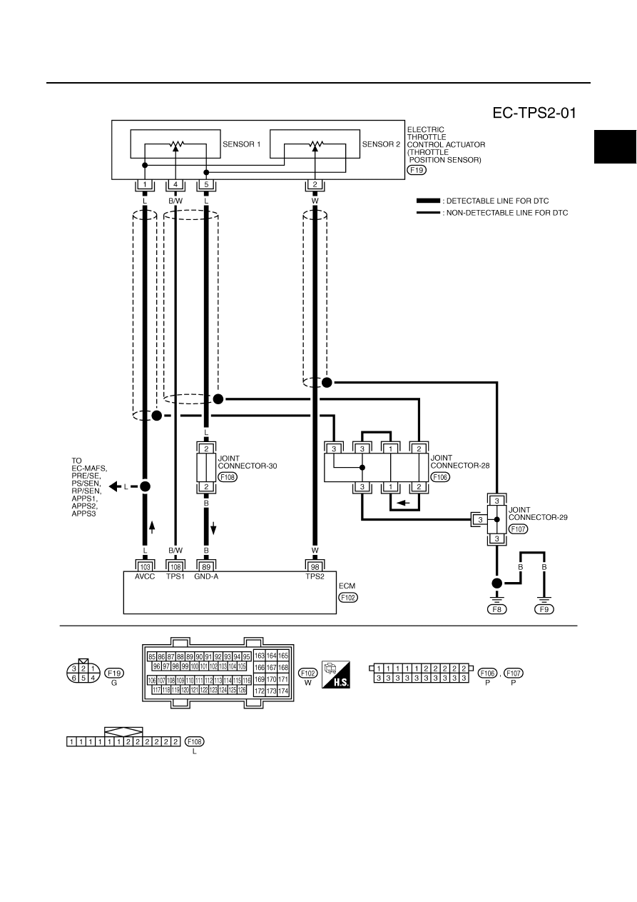
DTC P0122, P0123 TP SENSOR
EC-201
C
D
E
F
G
H
I
J
K
L
M
A
EC
Wiring Diagram
ABS002FZ
TBWA0282E
|
|
|
DTC P0122, P0123 TP SENSOR EC-201 C D E F G H I J K L M A EC Wiring Diagram ABS002FZ TBWA0282E |