Infiniti M45 (Y34). Manual - part 371


  Index      Infiniti     Infiniti M45 (Y34) - service repair manual 2004 year


Search            copyright infringement  


Content   ..  369  370  371  372   ..


Infiniti M45 (Y34). Manual - part 371


DTC P0037, P0038, P0057, P0058 HO2S2 HEATER

EC-173

C

D

E

F

G

H

I

J

K

L

M

A

EC

Component Inspection

ABS002EY

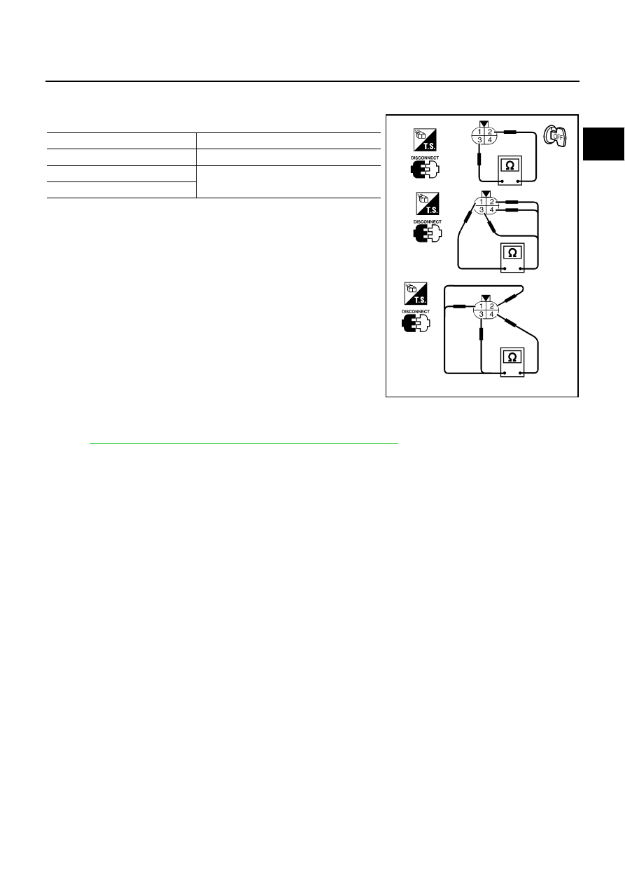
HEATED OXYGEN SENSOR 2 HEATER

1.

Check resistance between HO2S2 terminals as follows.

2.

If NG, replace heated oxygen sensor 2.

CAUTION:

Discard any heated oxygen sensor which has been dropped
from a height of more than 0.5 m (19.7 in) onto a hard sur-
face such as a concrete floor; use a new one.

Before installing new oxygen sensor, clean exhaust system
threads using Oxygen Sensor Thread Cleaner tool J-43897-
18 or J-43897-12 and approved anti-seize lubricant.

Removal and Installation

ABS002EZ

HEATED OXYGEN SENSOR 2

Refer to 

EM-22, "EXHAUST MANIFOLD AND THREE WAY CATALYST"

 .

Terminal No.

Resistance

2 and 3

5.0 - 7.0 

 [at 25

°

C (77

°

F)]

1 and 2, 3, 4


(Continuity should not exist)

4 and 1, 2, 3

SEF249Y

EC-174

DTC P0101 MAF SENSOR

DTC P0101 MAF SENSOR

PFP:22680

Component Description

ABS002F0

The mass air flow sensor is placed in the stream of intake air. It mea-
sures the intake flow rate by measuring a part of the entire intake
flow. It consists of a hot film that is supplied with electric current from
the ECM. The temperature of the hot film is controlled by the ECM a
certain amount. The heat generated by the hot film is reduced as the
intake air flows around it. The more air, the greater the heat loss.
Therefore, the ECM must supply more electric current to maintain
the temperature of the hot film as air flow increases. The ECM
detects the air flow by means of this current change.

CONSULT-II Reference Value in Data Monitor Mode

ABS002F1

Specification data are reference values.

On Board Diagnosis Logic

ABS002F2

NOTE:
If DTC P0101 is displayed with DTC P1229, first perform the trouble diagnosis for DTC P1229.
Refer to 

EC-531

 .

This self-diagnosis has the one trip detection logic.

SEC266C

MONITOR ITEM

CONDITION

SPECIFICATION

MAS A/F SE-B1

See 

EC-128, "TROUBLE DIAGNOSIS - SPECIFICATION VALUE"

 .

CAL/LD VALUE

Engine: After warming up

Selector lever: P or N

Air conditioner switch: OFF

No load

Idle

15% - 35%

2,500 rpm

10% - 35%

MASS AIRFLOW

Engine: After warming up

Selector lever: P or N

Air conditioner switch: OFF

No load

Idle

3.8 - 5.2 g·m/s

2,500 rpm

16.0 - 21.5 g·m/s

DTC No.

Trouble diagnosis name

DTC detecting condition

Possible cause

P0101
0101

Mass air flow sensor cir-
cuit range/performance 
problem

A)

A high voltage from the sensor is sent to ECM 
under light load driving condition.

Harness or connectors
(The sensor circuit is open or 
shorted.)

Mass air flow sensor

B)

A low voltage from the sensor is sent to ECM 
under heavy load driving condition.

Harness or connectors
(The sensor circuit is open or 
shorted.)

Intake air leaks

Mass air flow sensor

DTC P0101 MAF SENSOR

EC-175

C

D

E

F

G

H

I

J

K

L

M

A

EC

DTC Confirmation Procedure

ABS002F3

Perform PROCEDURE FOR MALFUNCTION A first.
If DTC cannot be confirmed, perform PROCEDURE FOR MALFUNCTION B.
NOTE:
If DTC Confirmation Procedure has been previously conducted, always turn ignition switch OFF and wait at
least 10 seconds before conducting the next test.

PROCEDURE FOR MALFUNCTION A

NOTE:
If engine will not start or stops soon, wait at least 10 seconds with engine stopped (Ignition switch ON) instead
of running engine at idle speed.

 With CONSULT-II

1.

Turn ignition switch ON.

2.

Select “DATA MONITOR” mode with CONSULT-II.

3.

Start engine and warm it up to normal operating temperature.

4.

Run engine for at least 10 seconds at idle speed.

5.

If DTC is detected, go to 

EC-178, "Diagnostic Procedure"

 .

 With GST

Follow the procedure With CONSULT-II above.

PROCEDURE FOR MALFUNCTION B

CAUTION:

Always drive vehicle at a safe speed.

 With CONSULT-II 

1.

Turn ignition switch ON.

2.

Start engine and warm it up to normal operating temperature.
If engine cannot be started, go to 

EC-178, "Diagnostic Procedure"

 .

3.

Select “DATA MONITOR” mode with CONSULT-II.

4.

Check the voltage of “MAS A/F SE-B1” with “DATA MONITOR”.

5.

Increases engine speed to about 4,000 rpm.

6.

Monitor the linear voltage rise in response to engine speed
increases.
If NG, go to 

EC-178, "Diagnostic Procedure"

 .

If OK, go to following step.

SEF174Y

SEF243Y

EC-176

DTC P0101 MAF SENSOR

7.

Maintain the following conditions for at least 10 consecutive sec-
onds.

8.

If DTC is detected, go to 

EC-178, "Diagnostic Procedure"

 .

Overall Function Check

ABS002F4

PROCEDURE FOR MALFUNCTION B

Use this procedure to check the overall function of the mass air flow sensor circuit. During this check, a DTC
might not be confirmed.

 With GST

1.

Start engine and warm it up to normal operating temperature.

2.

Select “MODE 1” with GST.

3.

Check the mass air flow sensor signal with “MODE 1”.

4.

Check for linear mass air flow sensor signal value rise in
response to increases to about 4,000 rpm in engine speed.

5.

If NG, go to 

EC-178, "Diagnostic Procedure"

 .

ENG SPEED

More than 2,000 rpm

THRTL SEN 1

More than 3V

THRTL SEN 2

More than 3V

Selector lever

Suitable position

Driving location

Driving vehicle uphill (Increased engine load) will help 
maintain the driving conditions required for this test.

PBIB0199E

SEF534P


Content   ..  369  370  371  372   ..