Infiniti M45 (Y34). Manual - part 368
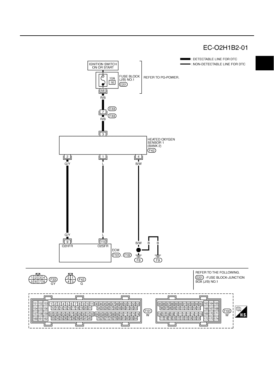
DTC P0031, P0032, P0051, P0052 HO2S1 HEATER
EC-161
C
D
E
F
G
H
I
J
K
L
M
A
EC
BANK 2
TBWA0268E
|
|
|
DTC P0031, P0032, P0051, P0052 HO2S1 HEATER EC-161 C D E F G H I J K L M A EC BANK 2 TBWA0268E |