Infiniti M45 (Y34). Manual - part 321


  Index      Infiniti     Infiniti M45 (Y34) - service repair manual 2004 year


Search            copyright infringement  


Content   ..  319  320  321  322   ..


Infiniti M45 (Y34). Manual - part 321


VEHICLE INFORMATION AND INTEGRATED SWITCH SYSTEM /WITHOUT 

NAVIGATION SYSTEM

DI-129

C

D

E

F

G

H

I

J

L

M

A

B

DI

3. 

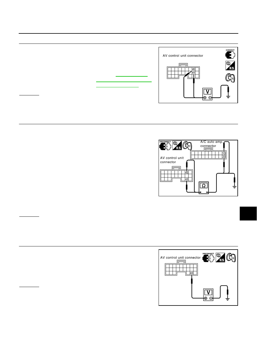
CHECK A/C-AV, AC-CLK COMMUNICATION SIGNAL

1.

Connect AV control unit connector.

2.

Turn ignition switch ON.

3.

Check voltage signal between AV control unit harness connector
M77 terminals 44 (W), 45 (B) and ground.

OK or NG

OK

>> Replace A/C auto amp.

NG

>> Replace AV control unit.

A/C Operation is Not Possible

AKS004OS

1. 

CHECK HARNESS

1.

Turn ignition switch OFF.

2.

Disconnect connectors of A/C auto amp. and AV control unit.

3.

Check continuity between A/C auto amp. harness connector
M119 terminal 10 (R) and AV control unit harness connector
M77 terminal 43 (R).

4.

Check continuity between A/C auto amp. harness connector
M119 terminal 20 (B) and AV control unit harness connector
M77 terminal 45 (B).

5.

Check continuity between AV control unit harness connector
M77 terminals 43 (R), 45 (B) and ground.

OK or NG

OK

>> GO TO 2.

NG

>>

Check connector housings for disconnected or loose terminals.

Repair harness or connector.

2. 

CHECK AV-A/C, AC-CLK COMMUNICATION SIGNAL

1.

Connect A/C auto amp. connector.

2.

Turn ignition switch ON.

3.

Check voltage between AV control unit harness connector M77
terminal 43 (R) and ground.

OK or NG

OK

>> GO TO 3.

NG

>> Replace A/C auto amplifier.

44 (W), 45 (B) - Ground

:Refer to 

DI-107, "Termi-

nals and Reference Value 
for AV Control Unit"

SKIA3746E

Continuity should exist.

Continuity should exist.

Continuity should not exist.

SKIA3747E

Approx. 5V

SKIA3748E

DI-130

VEHICLE INFORMATION AND INTEGRATED SWITCH SYSTEM /WITHOUT 

NAVIGATION SYSTEM

3. 

CHECK AV-A/C, AC-CLK COMMUNICATION SIGNAL

1.

Connect AV control unit connector.

2.

Turn ignition switch ON.

3.

Check voltage between AV control unit harness connector M77
terminals 43 (R), 45 (B) and ground with CONSULT-II or oscillo-
scope.

OK or NG

OK

>> Replace A/C auto amp.

NG

>> Replace AV control unit.

No Fuel Information is Displayed/No Warning Message is Displayed

AKS0040G

1. 

CHECK HARNESS

1.

Disconnect connectors of AV control unit, combination meter and BCM.

2.

Check continuity between AV control unit harness connector
M77 terminal 34 (LG) and combination meter harness connector
M42 terminal 56 (LG).

3.

Check continuity between AV control unit harness connector
M77 terminal 35 (PU) and combination meter harness connector
M42 terminal 57 (PU).

4.

Check continuity between AV control unit harness connector
M77 terminals 34 (LG), 35 (PU) and ground.

OK or NG

OK

>> GO TO 2.

NG

>>

Check connector housings for disconnected or loose terminals.

Repair harness or connector.

2. 

CHECK COMMUNICATION SIGNAL (AV-ME)

1.

Connect combination meter connector, BCM connector and AV control unit connector.

2.

Turn ignition switch ON.

3.

Check voltage signal between AV control unit harness connector
M77 terminal 34 (LG) and ground with CONSULT-II or oscillo-
scope.

OK or NG

OK

>> GO TO 3.

NG

>> Replace AV control unit.

43 (R), 45 (B) - Ground

: Refer to 

DI-107, "Terminals 

and Reference Value for AV 
Control Unit"

SKIA3749E

Continuity should exist.

Continuity should exist.

Continuity should not exist.

SKIA4204E

34 (LG) - Ground

: Refer to 

DI-107, "Terminals and 

Reference Value for AV Control 
Unit"

 .

PKIA6798E

VEHICLE INFORMATION AND INTEGRATED SWITCH SYSTEM /WITHOUT 

NAVIGATION SYSTEM

DI-131

C

D

E

F

G

H

I

J

L

M

A

B

DI

3. 

CHECK COMMUNICATION SIGNAL (ME-AV)

1.

Turn ignition switch to ON and display “VEHICLE ELECTRONIC
SYSTEMS” screen.

2.

Check voltage signal between AV control unit harness connector
M77 terminal 35 (PU) and ground with CONSULT-II or oscillo-
scope.

OK or NG

OK

>> Replace AV control unit.

NG

>> Replace combination meter.

Vehicle Condition Setting is Not Possible

AKS004OT

1. 

CHECK HARNESS

1.

Disconnect connectors of AV control unit, combination meter and BCM.

2.

Check continuity AV control unit harness connector M77 termi-
nal 34 (LG) and BCM harness connector M4 terminal 31 (LG).

3.

Check continuity AV control unit harness connector M77 termi-
nal 35 (PU) and BCM harness connector M4 terminal 30 (PU).

4.

Check continuity between AV control unit harness connector
M77 terminals 34 (LG), 35 (PU) and ground.

OK or NG

OK

>> GO TO 2.

NG

>>

Check connector housings for disconnected or loose terminals.

Repair harness or connector.

2. 

CHECK COMMUNICATION SIGNAL (AV-ME)

1.

Connect AV control unit connector, combination meter connector
and BCM connector.

2.

Turn ignition switch ON.

3.

Check voltage signal between AV control unit harness connector
M77 terminal 34 (LG) and ground with CONSULT-II or oscillo-
scope.

OK or NG

OK

>> GO TO 3.

NG

>> Replace AV control unit.

35 (PU) - Ground

: Refer to 

DI-107, "Terminals and 

Reference Value for AV Control 
Unit"

 .

PKIA6799E

Continuity should exist.

Continuity should exist.

Continuity should not exist.

SKIA3606E

34 (LG) - Ground

: Refer to 

DI-107, "Terminals and 

Reference Value for AV Control 
Unit"

 .

PKIA6798E

DI-132

VEHICLE INFORMATION AND INTEGRATED SWITCH SYSTEM /WITHOUT 

NAVIGATION SYSTEM

3. 

CHECK COMMUNICATION SIGNAL (ME-AV)

1.

Turn ignition switch to ON and display “VEHICLE ELECTRONIC
SYSTEMS” screen.

2.

Check voltage signal between AV control unit harness connector
M77 terminal 35 (PU) and ground with CONSULT-II or oscillo-
scope.

OK or NG

OK

>> Replace AV control unit.

NG

>> Replace BCM.

Multifunction Switch does Not Operate

AKS004DJ

1. 

MULTIFUNCTION SWITCH SELF-DIAGNOSIS

Perform multifunction switch self-diagnosis. Refer to 

DI-119, "Multifunction Switch Self-Diagnosis Function"

 .

Is self-diagnosis result OK?

OK

>> GO TO 2.

NG

>> Replace multifunction switch.

2. 

CHECK POWER AND GROUND CIRCUIT

Check power and ground circuit. Refer to 

DI-122, "Inspection of Multifunction Switch for Power Supply and

Ground Circuit"

 .

OK or NG

OK

>> GO TO 3.

NG

>> Repair harness or connector.

3. 

COMMUNICATION CIRCUIT SELF-DIAGNOSIS

Perform the self-diagnosis mode in the self-diagnosis function (If the self-diagnosis cannot be activated with
the multifunction switch, check with CONSULT-II). Refer to 

DI-113, "Self-Diagnosis Mode"

 .

Is self-diagnosis result OK?

OK

>> Replace display.

NG

>> With the self-diagnosis results, check the malfunction part.

Multifunction Switch Indicator does not Illuminate

AKS004DK

1. 

MULTIFUNCTION SWITCH SELF-DIAGNOSIS

Perform the multifunction switch self-diagnosis. Refer to 

DI-119, "Multifunction Switch Self-Diagnosis Func-

tion"

 .

Is the self-diagnosis result OK?

OK

>> Replace switch of the malfunctioning indicator.

NG

>> Replace multifunction switch.

35 (PU) - Ground

: Refer to 

DI-107, "Terminals and 

Reference Value for AV Control 
Unit"

 .

PKIA6799E


Content   ..  319  320  321  322   ..