Infiniti M45 (Y34). Manual - part 230


  Index      Infiniti     Infiniti M45 (Y34) - service repair manual 2004 year


Search            copyright infringement  


Content   ..  228  229  230  231   ..


Infiniti M45 (Y34). Manual - part 230


VEHICLE SECURITY (THEFT WARNING) SYSTEM

BL-145

C

D

E

F

G

H

J

K

L

M

A

B

BL

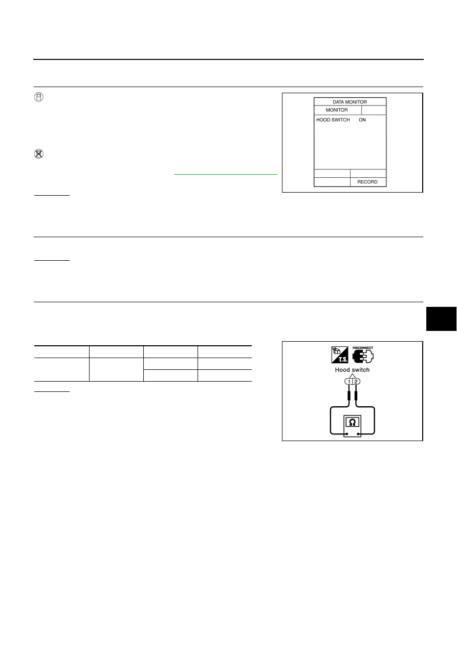
1 – 2 CHECK HOOD SWITCH

1. 

CHECK HOOD SWITCH INPUT SIGNAL

 With CONSULT

II

Check “HOOD SWITCH” in “DATA MONITOR” mode with CON-
SULT

II.

 Without CONSULT

II

Check hood switch in Switch monitor mode.
Refer to Remote keyless entry system, 

BL-79, "SWITCH MONITOR"

.
OK or NG

OK

>> Hood switch is OK.

NG

>> GO TO 2.

2. 

CHECK HOOD SWITCH CONDITION

Check hood switch and hood fitting condition.

OK or NG

OK

>> GO TO 3.

NG

>> Adjust installation of hood switch.

3. 

CHECK HOOD SWITCH

1.

Turn ignition switch OFF.

2.

Disconnect hood switch connector.

3.

Check continuity between hood switch terminals.

OK or NG

OK

>> Check the following. Repair or replace following item, 

when there is a malfunction.

Hood switch ground circuit

Harness for open or short between hood switch and
BCM

NG

>> Replace hood switch.

When hood is open

: HOOD SW ON

When hood is closed

: HOOD SW OFF

PIIA0343E

Connector

Terminal

Condition

Continuity

E54

 2

Closed

No

Open

Yes

PIIA2800E

BL-146

VEHICLE SECURITY (THEFT WARNING) SYSTEM

1 – 3 CHECK TRUNK ROOM LAMP SWITCH

1. 

CHECK TRUNK ROOM LAMP SWITCH INPUT SIGNAL

 With CONSULT

II

Check “TRUNK SWITCH” in “DATA MONITOR” mode with CONSULT

II.

 Without CONSULT

II

Check trunk room lamp switch in Switch monitor mode.
Refer to Remote keyless entry system

BL-79, "SWITCH MONITOR"

.

OK or NG

OK

>> Trunk room lamp switch is OK.

NG

>> GO TO 2.

2. 

CHECK TRUNK ROOM LAMP SWITCH

1.

Turn ignition switch OFF.

2.

Disconnect trunk room lamp switch connector.

3.

Check continuity between trunk room lamp switch terminals.

OK or NG

OK

>> Check the following. Repair or replace following item, 

when there is a malfunction.

Trunk room lamp switch ground circuit

Harness for open or short between trunk room lamp
switch and BCM

NG

>> Replace trunk room lamp switch.

Diagnostic Procedure 2

AIS001F0

CHECK SECURITY INDICATOR LAMP

1. 

INDICATOR LAMP ACTIVE TEST

With CONSULT

II

Check “INDICATOR LAMP” in “ACTIVE TEST” mode with CONSULT

II.

NOTE:
If CONSULT-II is not available, skip this procedure and go to the
next procedure.

OK or NG

OK

>> Security indicator lamp is OK.

NG

>> GO TO 2.

When trunk lid is open

: TRUNK SW ON

When trunk lid is closed

: TRUNK SW OFF

PIIA0345E

Connector

Terminal

Condition

Continuity

B266

 2

Closed

No

Open

Yes

PIIA2801E

Perform operation shown on display.
Indicator lamp should illuminate.

PIIA0347E

VEHICLE SECURITY (THEFT WARNING) SYSTEM

BL-147

C

D

E

F

G

H

J

K

L

M

A

B

BL

2. 

CHECK INDICATOR LAMP

1.

Turn ignition switch OFF.

2.

Check indicator lamp condition.

OK or NG

OK

>> GO TO 3.

NG

>> Replace indicator lamp.

3. 

CHECK POWER SUPPLY CIRCUIT FOR INDICATOR LAMP

1.

Disconnect security indicator lamp connector.

2.

Check voltage between indicator lamp connector M73 terminal 2 (Y/G) and ground.

OK or NG

OK

>> Check harness for open or short between security indi-

cator lamp and BCM.

NG

>> Check the following.

10A fuse [No. 6, located in fuse block (J/B) No. 1]

Harness for open or short between security indicator
lamp and fuse.

Diagnostic Procedure 3

AIS001F1

CHECK DOOR UNLOCK SENSOR 

1. 

CHECK DOOR UNLOCK SENSOR INPUT SIGNAL

 With CONSULT-II

Check door unlock sensor “LOCK SIG” in “DATA MONITOR” mode with CONSULT-II.

 Without CONSULT-II

Check door lock knob operation in Switch monitor mode.
Refer to Remote keyless entry system, 

BL-79, "SWITCH MONITOR"

.

OK or NG

OK

>> Door unlock sensor is OK.

NG

>> GO TO 2. (Diagnose the malfunctioning door parts in

accordance with the following charts.)

2 (Y/G) – Ground

: Battery voltage

PIIA2802E

When door is locked

: LOCK SIG LOCK

When door is unlocked

: LOCK SIG UNLK

PIIA2803E

BL-148

VEHICLE SECURITY (THEFT WARNING) SYSTEM

2. 

CHECK DOOR UNLOCK SENSOR INPUT SIGNAL

1.

Turn ignition switch OFF.

2.

Disconnect door lock actuator connector.

3.

Check voltage between each door control unit and ground.

OK or NG

OK

>> GO TO 3.

NG

>> Replace malfunctioning door control unit.

3. 

CHECK DOOR UNLOCK SENSOR SIGNAL CIRCUIT

1.

Disconnect door control unit connector.

2.

Check continuity between door control unit and door lock actuator (door unlock sensor).

3.

Check continuity between door control unit and ground.

OK or NG

OK

>> GO TO 4.

NG

>> Repair or replace malfunctioning harness.

 Door control unit connector

Terminal (Wire color)

Voltage (V)

Front door

 Driver side: D8

6 (G/Y) 

 ground

Approx. 5

Passenger side: D38

2 (G/Y) 

 ground

Rear door

LH: D58

RH: D78

PIIA2860E

 Connector

Terminal 

(wire color)

Connector

Terminal 

(Wire color)

Continuity

Driver side: 
D8

 6 (G/Y)

D11

2 (G/Y)

Should exist

Passenger 
side: D38

2 (G/Y)

D41

Rear LH: 
D58

D61

Rear RH: 
D78

D81

 Connector

Terminal (wire color)

Continuity

Driver side: D8

 6 (G/Y) 

 ground

Should not exist

Passenger side: D38

2 (G/Y) 

 ground

Rear LH: D58

Rear RH: D78

PIIA2857E

PIIA2858E


Content   ..  228  229  230  231   ..