Infiniti M45 (Y34). Manual - part 225


  Index      Infiniti     Infiniti M45 (Y34) - service repair manual 2004 year


Search            copyright infringement  


Content   ..  223  224  225  226   ..


Infiniti M45 (Y34). Manual - part 225


TRUNK CLOSURE SYSTEM

BL-125

C

D

E

F

G

H

J

K

L

M

A

B

BL

4. 

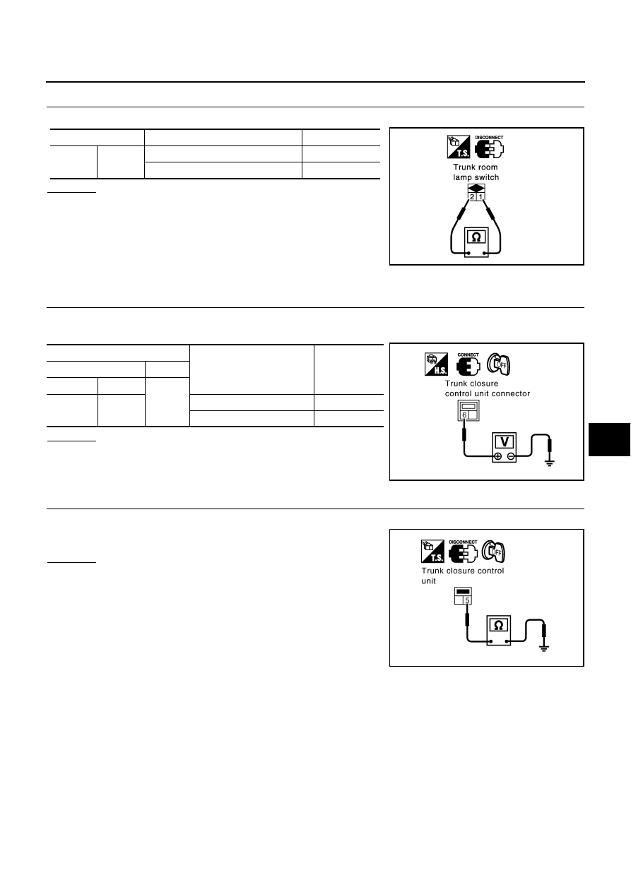
CHECK TRUNK ROOM LAMP SWITCH 

Check continuity between trunk room lamp switch terminals 1 and 2.

OK or NG

OK

>> Trunk room lamp switch is OK.

NG

>> Replace trunk room lamp switch.

Check Trunk Closure Motor

AIS001MR

1. 

CHECK TRUNK CLOSURE CONTROL UNIT OUTPUT SIGNAL

1.

Turn ignition switch OFF.

2.

Check voltage between trunk closure control unit connector and ground.

OK or NG

OK

>> GO TO 2.

NG

>> Replace trunk closure control unit.

2. 

CHECK TRUNK CLOSURE MOTOR GROUND CIRCUIT 

Check continuity between trunk closure control unit connector B601 terminal 5 and ground.

OK or NG

OK

>> Replace trunk closure motor.

NG

>> Replace trunk closure control unit.

Terminals

Condition

Continuity

1

2

Trunk is closed

No

Trunk is opened

Yes

PIIA2811E

Terminals

Condition

Voltage (V)

(Approx.)

(+)

(–)

Connector

Terminal

Ground

B601

6

Closure motor is in operation

Battery voltage

Other than the above

0

PIIB0827E

5 – Ground

: Continuity should exist.

PIIB0828E

BL-126

VEHICLE SECURITY (THEFT WARNING) SYSTEM

VEHICLE SECURITY (THEFT WARNING) SYSTEM

PFP:28491

Component Parts Harness Connector Location

AIS001ER

PIIA2865E

VEHICLE SECURITY (THEFT WARNING) SYSTEM

BL-127

C

D

E

F

G

H

J

K

L

M

A

B

BL

System Description

AIS001ES

DESCRIPTION
Setting the Vehicle Security System

Disarmed phase

When the vehicle is being driven or when doors or trunk lid is open, the vehicle security system is set in
the disarmed phase on the assumption that the owner is inside or near the vehicle.

Pre-armed phase and armed phase

The vehicle security system turns into the “pre-armed” phase when hood, trunk lid and all doors are
closed and locked by electronic key. The security indicator lamp illuminates for 30 seconds. Then, the sys-
tem automatically shifts into the “armed” phase.

Canceling the Vehicle Security System

When the following 1 or 2 operation is performed, the armed phase is canceled.

1.

Unlock the doors with the electronic key or emergency key.

2.

Open the trunk lid with the electronic key or emergency key. When the trunk lid is closed after opening the
trunk lid with the electronic key, the system returns to the armed phase.

Activating the Alarm Operation of the Vehicle Security System

Make sure the system is in the armed phase.
When the following operation 1, 2 or 3 is performed, the system sounds the horn and flashes the head-lamps
for about 50 seconds.

1.

Engine hood, trunk lid or any door is opened before unlocking door with electronic key or emergency key.

2.

Door is unlocked without using electronic key or emergency key.

3.

Trunk lid is opened without using electronic key or emergency key.

POWER SUPPLY
Power is Supplied at All Times

through 10A fuse [No. 6, located in the fuse block (J/B) No. 1]

to security indicator lamp terminal 2.

Power is Supplied at All Times

through 10A fuse [No. 3, located in the fuse block (J/B) No. 1]

to BCM terminal 105.

With the Ignition Switch in the ACC or ON Position, Power is Supplied

through 10A fuse [No. 21, located in the fuse block (J/B) No. 1]

to BCM terminal 60.

With the Ignition Switch in the ON or START Position, Power is Supplied

through 10A fuse [No. 1, located in the fuse block (J/B) No. 1]

to BCM terminal 68.

BCM is connected to LCU01 as DATA LINE A – 3.

INITIAL CONDITION TO ACTIVATE THE SYSTEM

The operation of the vehicle security system is controlled by the doors, hood and trunk lid.

PIIA2866E

BL-128

VEHICLE SECURITY (THEFT WARNING) SYSTEM

To activate the vehicle security system, BCM must receive signals indicating the doors, hood and trunk lid are
closed and the doors are locked.
When the door is open, BCM terminal 33 (rear LH door), 37 (passenger door), 142 (driver door) or 143 (rear
RH door) receives a ground signal from each door switch.
When a driver door is unlocked, driver door control unit (LCU01) terminal 6 receives a ground signal from ter-
minal 2 of driver side door unlock sensor.
When the passenger, rear LH or RH door is unlocked, passenger, rear LH or RH door control unit terminal 2
receives a ground signal from terminal 2 of each door unlock sensor.
When the hood is open, BCM terminal 122 receives a ground signal

from terminals 1 and 2 of the hood switch

through body grounds E42 and E62.

When the trunk lid is open, BCM terminal 146 receives a ground signal

from terminals 1 and 2 of the trunk room lamp switch

through body grounds B217, B256.

When the doors are locked with electronic key and none of the described conditions exist, the vehicle security
system will automatically shift to armed phase.

VEHICLE SECURITY SYSTEM ACTIVATION (WITH KEY OR ELECTRONIC KEY USED TO LOCK 
DOORS)

If the emergency key is used to lock doors, driver side door control unit (LCU01 terminal 10 receives a ground
signal

from terminals 2 and 3 of the front door key cylinder switch (driver side).

through body grounds M24 and M114

If this signal or lock signal from electronic key is received by BCM, the vehicle security system will activate
automatically.
Once the vehicle security system has been activated, BCM terminal 65 supplies ground to terminal 1 of the
security indicator lamp.
The security indicator lamp will illuminate for approximately 30 seconds and then blink.
Now the vehicle security system is in armed phase.

VEHICLE SECURITY SYSTEM ALARM OPERATION

The vehicle security system is triggered by

opening a door

opening the trunk lid

opening the hood

unlocking door without using the electronic key or emergency key.

The vehicle security system will be triggered once the system is in armed phase,

when BCM receives a ground signal at terminal 33, 37, 142, 143 (door switch), 146 (trunk room lamp
switch) or 122 (hood switch) 

when driver door control unit (LCU01) receives a ground signal at terminal 6 (driver side door unlock sen-
sor) 

when passenger, rear LH, RH door control unit receives a ground signal at terminal 2 (each door unlock
sensor)

Power is supplied at all times

to headlamp relay-1 terminal 2 and

through 15A fuse [No. 73, located in the fuse, fusible link and relay block (J/B)]

to headlamp relay-2 terminal 1 and

through 10A fuse [No. 78, located in the fuse, fusible link and relay block (J/B)]

to security horn relay terminal 2.

When the vehicle security system is triggered, ground is supplied intermittently

from BCM terminal 5 (lamp relay) and 127 (security horn relay) 

to headlamp relay-1 terminal 1 and

to headlamp relay-2 terminal 2 and

to security horn relay terminal 1.


Content   ..  223  224  225  226   ..