Infiniti M45 (Y34). Manual - part 218


  Index      Infiniti     Infiniti M45 (Y34) - service repair manual 2004 year


Search            copyright infringement  


Content   ..  216  217  218  219   ..


Infiniti M45 (Y34). Manual - part 218


REMOTE KEYLESS ENTRY SYSTEM

BL-97

C

D

E

F

G

H

J

K

L

M

A

B

BL

Check Map Lamp Function

AIS002BV

1. 

CHECK MAP LAMP FUNCTION

When map lamp switch is in “DOOR” position, open the front door (LH or RH).

OK or NG

OK

>> Map lamp function circuit is OK.

NG

>> Check map lamp circuit. Refer to 

LT-128, "INTERIOR ROOM LAMP"

 .

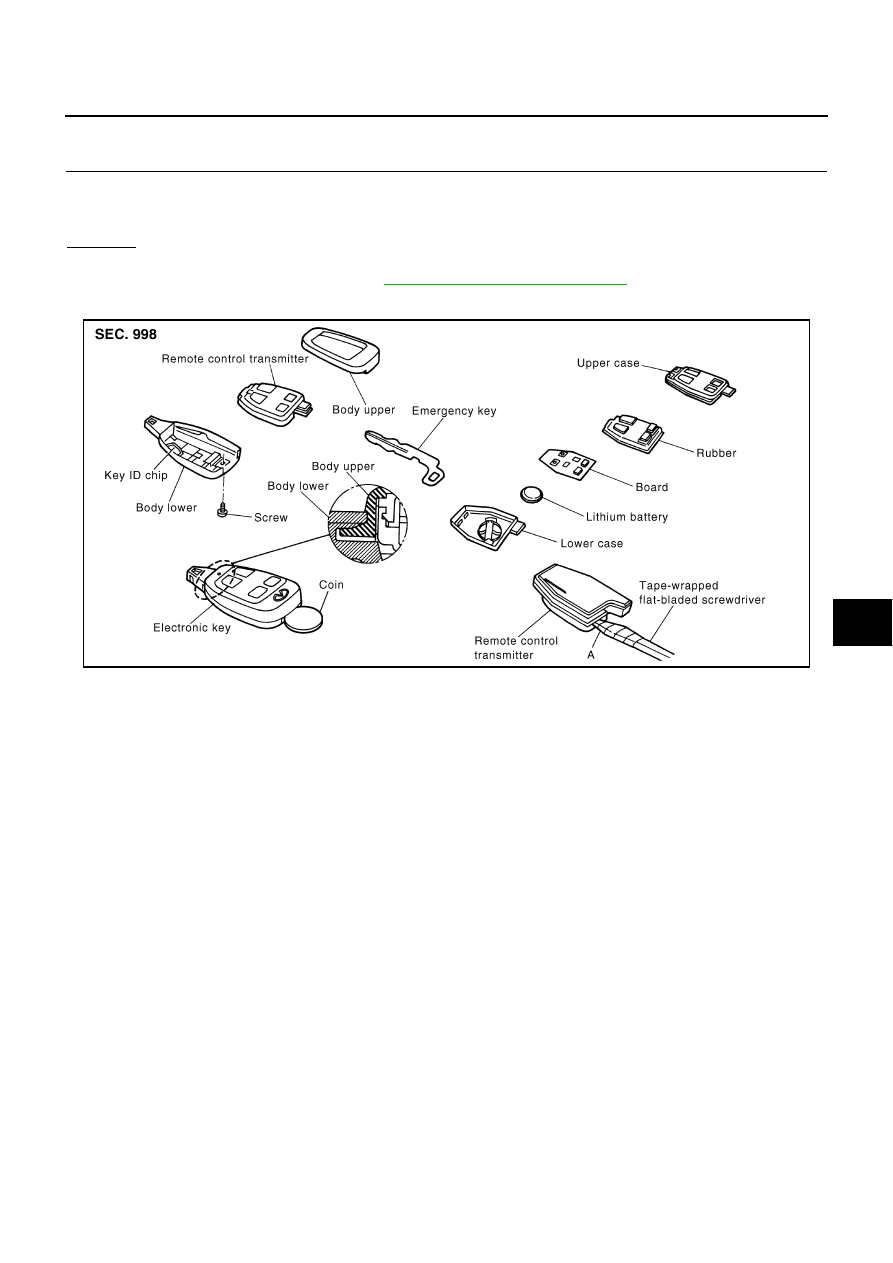
Electronic Key Battery Replacement

AIS001E7

1.

Remove the mounting screw on the back side of the electronic key, and insert a slotted coin into the emer-
gency key slot. Twist the coin to separate the upper body from the lower body. Then take out the elec-
tronic key transmitter.

CAUTION:

During disassembly, do not impact the transponder on the lower body.

2.

Insert a slotted screwdriver wrapped with tape into the electronic key transmitter (A) and twist the screw-
driver to disassemble the transmitter.

3.

Replace the battery fixed on the lower body. Be sure to install new battery properly with the positive side
facing the lower case.

CAUTION:

During disassembly, be careful not to touch the board surface. Visually check the board for
color change (bluish) and deposit.

When replacing the battery, keep the electrode off foreign materials such as dust and grease.

4.

After replacing the battery, engage the tab on the side of the body while being careful not to pinch the rub-
ber, and assemble the upper and lower bodies.

5.

While being careful of engagement between the upper and lower bodies at the end, assemble the elec-
tronic key transmitter, and tighten it with screws.

CAUTION:

After replacing the battery, be sure to check that the door locking operates normally using the
electronic key.

Map lamp should illuminate.

PIIA3472E

BL-98

REMOTE KEYLESS ENTRY SYSTEM

CHECK ELECTRONIC KEY BATTERY

Remove battery and measure voltage between battery positive and negative terminals.

 Voltage

: 2.5V – 3.0V

OCC0607D

REMOTE KEYLESS ENTRY SYSTEM

BL-99

C

D

E

F

G

H

J

K

L

M

A

B

BL

ID Code Entry Procedure

AIS001E8

PROCEDURE 1 (WITHOUT CONSULT-II)

SEL170Y

BL-100

REMOTE KEYLESS ENTRY SYSTEM

NOTE:

If a electronic key is lost, the ID code of the lost electronic key must be erased to prevent unauthorized
use. A specific ID code can be erased with CONSULT-II. However, when the ID code of a lost electronic
key is not known, all controller ID codes should be erased. After all ID codes are erased, the ID codes of
all remaining and/or new remote controllers must be re-registered. To erase all ID codes in memory, regis-
ter one ID code (electronic key) four times. After all ID codes are erased, the ID codes of all remaining
and/or new electronic keys must be re-registered.

When registering an additional electronic key, the existing ID codes in memory may or may not be erased.
If four ID codes are stored in memory, when an additional code is registered, only the oldest code is
erased. If less than four ID codes are stored in memory, when an additional ID code is registered, the new
ID code is added and no ID codes are erased.

If you need to activate more than two additional new electronic keys, repeat the procedure “Additional ID
code entry” for each new electronic key.

Entry of maximum four ID codes is allowed. When more than four ID codes are entered, the oldest ID
code will be erased.

Even if same ID code that is already in the memory is input, the same ID code can be entered. The code
is counted as an additional code.

PROCEDURE 2 (WITH CONSULT-II)

NOTE:
If a electronic key is lost, the ID code of the lost electronic key must be erased to prevent unauthorized use.
When the ID code of a lost electronic key is not known, all controller ID codes should be erased. After all ID
codes are erased, the ID codes of all remaining and/or new remote controllers must be re-registered.

1.

Turn ignition switch OFF.

2.

Connect “CONSULT-II” and “CONSULT-II CONVERTER” to the
data link connector.

3.

Turn ignition switch ON.

4.

Touch “START (NISSAN BASED VHCL)”.

PBIB0196E

MBIB0233E


Content   ..  216  217  218  219   ..