Infiniti M45 (Y34). Manual - part 216


  Index      Infiniti     Infiniti M45 (Y34) - service repair manual 2004 year


Search            copyright infringement  


Content   ..  214  215  216  217   ..


Infiniti M45 (Y34). Manual - part 216


REMOTE KEYLESS ENTRY SYSTEM

BL-89

C

D

E

F

G

H

J

K

L

M

A

B

BL

2. 

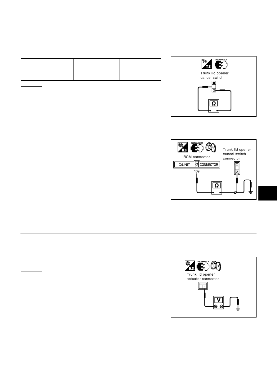
CANCEL SWITCH INSPECTION

Check continuity between trunk lid opener cancel switch terminals 1 and 2.

OK or NG

OK

>> GO TO 3.

NG

>> Replace trunk lid opener cancel switch.

3. 

CHECK HARNESS CONTINUITY

1.

Disconnect BCM connector.

2.

Check continuity between BCM connector M4 terminal 109 (Y/
B) and trunk lid opener cancel switch connector M117 terminal
2 (Y/B).

3.

Check continuity between BCM connector M4 terminal 109 (Y/
B) and ground.

OK or NG

OK

>> Trunk lid opener cancel switch circuit is OK.

NG

>> Repair or replace harness.

Check Trunk Lid Opener Actuator

AIS001E2

Before carrying out the following diagnosis, check that the trunk opener cancel switch is turned ON.

1. 

CHECK POWER SUPPLY CIRCUIT

1.

Turn ignition switch OFF.

2.

Disconnect trunk lid opener actuator connector.

3.

Check voltage between trunk lid opener actuator connector B265 terminal 1 (PU/W) and ground.

OK or NG

OK

>> GO TO 2.

NG

>> Check the following.

10A fuse [No.15, located in the fuse block (J/B) No. 1]

Harness for open and short between trunk lid opener
actuator and fuse

Connector

Terminal

Condition

Continuity

M117

1  – 2

Switch: ON

Yes

Switch: OFF

No

PIIA2824E

109 (Y/B) – 2 (Y/B)

: Continuity should exist.

109 (Y/B) – Ground

: Continuity should not exist.

PIIA2825E

1 (PU/W) – Ground

: Battery voltage

PIIA3085E

BL-90

REMOTE KEYLESS ENTRY SYSTEM

2. 

CHECK TRUNK LID OPENER ACTUATOR 

Check continuity between trunk lid opener actuator terminals 1 and 2.

OK or NG

OK

>> GO TO 3.

NG

>> Replace trunk lid opener actuator.

3. 

CHECK TRUNK LID OPENER RELAY CIRCUIT

1.

Remove electronic key from ignition key cylinder.

2.

Connect trunk lid opener actuator connector.

3.

Check voltage between trunk lid opener actuator connector B265 terminal 2 (SB) and ground.

OK or NG

OK

>> Trunk lid opener actuator circuit is OK.

NG

>> Check the following.

Harness between trunk lid opener actuator and trunk
lid opener relay.

Harness between trunk lid opener relay and ground.

Trunk lid opener relay

Check Trunk Open Signal

AIS001E3

1. 

CHECK BCM OUTPUT SIGNAL

1.

Remove electronic key from ignition key cylinder.

2.

Check voltage between BCM connector M4 terminal 109 (Y/B) and ground.

OK or NG

OK

>> BCM output signal (trunk open signal) is OK.

NG

>> Replace BCM.

1 – 2

: Continuity should exist.

PIIA2827E

Terminal

(Wire color)

Condition

Voltage (V)

(Approx.)

2 (SB) – Ground

Electronic key: Trunk open switch ON

0 (0.7 seconds)

Electronic key: Trunk open switch OFF

Battery voltage

PIIA3084E

Terminal

(Wire color)

Condition

Voltage (V)

(Approx.)

109 (Y/B) – Ground

Electronic key: Trunk open switch ON

0V (0.7 seconds)

Electronic key: Trunk open switch OFF

Battery voltage

PIIA2828E

REMOTE KEYLESS ENTRY SYSTEM

BL-91

C

D

E

F

G

H

J

K

L

M

A

B

BL

Check Security Horn Operation

AIS001E4

1. 

CHECK SECURITY HORN CHIRP OPERATION

With CONSULT

II

1.

Check security horn chirp “HORN” in “ACTIVE TEST” mode with CONSULT

II.

2.

Perform operation shown on display.

Without CONSULT

II

1.

Disconnect BCM connector.

2.

Apply ground to BCM connector E204 terminal 127 (P/L). 

OK or NG

OK

>> Security horn alarm is OK.

NG

>> GO TO 2.

2. 

CHECK SECURITY HORN RELAY

Check security horn relay condition.

OK or NG

OK

>> GO TO 3.

NG

>> Replace security horn relay.

3. 

CHECK POWER SUPPLY FOR SECURITY HORN RELAY

1.

Disconnect security horn relay connector.

2.

Check voltage between security horn relay connector E77 terminal 2 (Y/B) and ground.

OK or NG

OK

>> GO TO 4.

NG

>> Check the following.

10A fuse [No. 78, located in the fuse, fusible link and
relay block (J/B)]

Harness for open or short between security horn relay
and fuse.

Security horn should sound.

SEL945W

Security horn should sound.

PIIA0359E

2 (Y/B) – Ground

: Battery voltage

PIIA2829E

BL-92

REMOTE KEYLESS ENTRY SYSTEM

4. 

CHECK SECURITY HORN RELAY CIRCUIT

1.

Disconnect BCM and security horn relay connector.

2.

Check continuity between BCM connector E204 terminal 127 (P/L) and security horn relay connector E77
terminal 1 (P/L).

OK or NG

OK

>> GO TO 5.

NG

>> Repair or replace harness.

5. 

CHECK SECURITY HORN RELAY CIRCUIT

1.

Disconnect security horn relay and security horn connector.

2.

Check continuity between security horn relay connector E77 terminal 3 (P/B) and security horn connector
E30 terminal 1 (P/B).

OK or NG

OK

>> Replace security horn.

NG

>> Repair or replace harness.

127 (P/L) – 1 (P/L)

: Continuity should exist.

PIIA2840E

3 (P/B) – 1 (P/B)

: Continuity should exist.

PIIA2841E


Content   ..  214  215  216  217   ..