Infiniti M45 (Y34). Manual - part 166
REFRIGERANT LINES
ATC-149
C
D
E
F
G
H
I
K
L
M
A
B
ATC
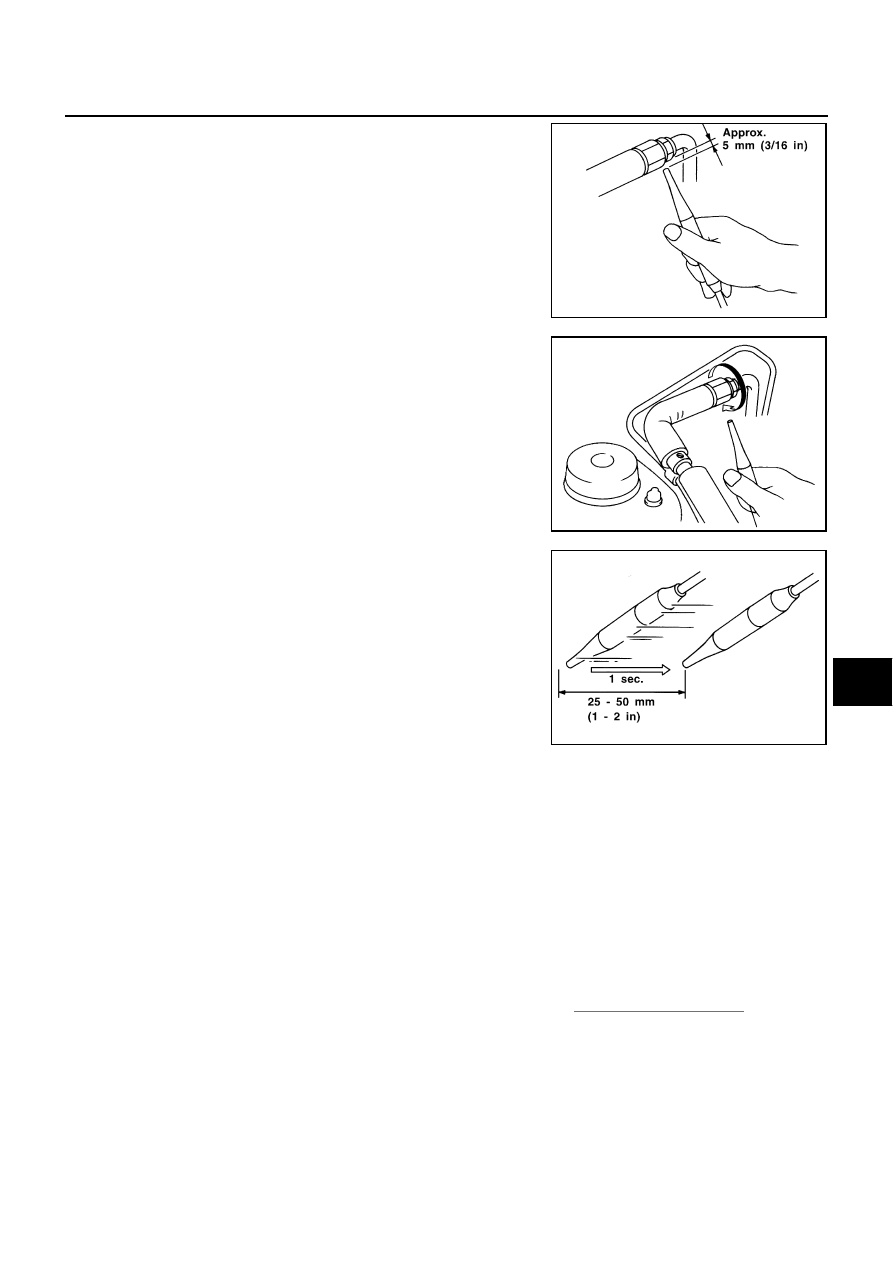
1.
Position probe approximately 5 mm (3/16 in) away from point to
be checked.
2.
When testing, circle each fitting completely with probe.
3.
Move probe along component approximately 25 to 50 mm (1 to
2 in)/sec.
CHECKING PROCEDURE
To prevent inaccurate or false readings, make sure there is no refrigerant vapor, shop chemicals, or cigarette
smoke in the vicinity of the vehicle. Perform the leak test in calm area (low air/wind movement) so that the
leaking refrigerant is not dispersed.
1.
Turn engine OFF.
2.
Connect a suitable A/C manifold gauge set to the A/C service ports.
3.
Check if the A/C refrigerant pressure is at least 345 kPa (3.52 kg/cm
2
, 50 psi) above 16
°
C (61
°
F). If less
than specification, recover/evacuate and recharge the system with the specified amount of refrigerant.
NOTE:
At temperatures below 16
°
C (61
°
F), leaks may not be detected since the system may not reach 345 kPa
(3.52 kg/cm
2
, 50 psi).
4.
Conduct the leak test from the high-pressure side (compressor discharge a to evaporator inlet f) to the
low-pressure side (evaporator drain hose g to shaft seal k). Refer to
. Perform a
leak check for the following areas carefully. Clean the component to be checked and move the leak detec-
tion probe completely around the connection/component.
Compressor
Check the fitting of high- and low-pressure hoses, relief valve and shaft seal.
Liquid tank
Check the refrigerant connection.
Service valves
Check all around the service valves. Ensure service valve caps are secured on the service valves (to pre-
vent leaks).
SHA707EA
SHA706E
SHA708EA