Infiniti M45 (Y34). Manual - part 105
SHIFT CONTROL SYSTEM
AT-305
D
E
F
G
H
I
J
K
L
M
A
B
AT
REMOVAL
1.
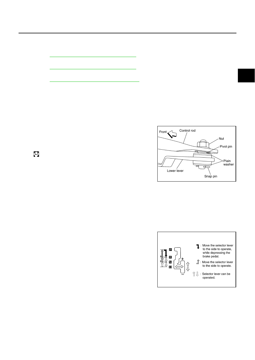
Disconnect lower lever of control device and control rod.
2.
Remove console finisher.
●
IP-10, "INSTRUMENT PANEL ASSEMBLY"
.
3.
Remove console box assembly.
●
IP-10, "INSTRUMENT PANEL ASSEMBLY"
.
4.
Remove rear ventilator duct.
●
ATC-132, "Removal of Rear Ventilator Ducts"
5.
Disconnect control device harness connector.
6.
Remove control device assembly.
INSTALLATION
Install in reverse order of removal. Be careful of the following:
●
After installation is completed, adjust and check A/T position.
Adjustment of A/T Position
ACS001GC
1.
Loosen nut of pivot pin.
2.
Place PNP switch and selector lever in “P” position.
3.
While pressing lower lever toward rear of vehicle (in P-position
direction), tighten nut to specified torque.
Checking of A/T Position
ACS001GD
1.
Place selector lever in “P” position, and turn ignition switch ON (engine stop).
2.
Check that selector lever can be shifted to other than “P” position when brake pedal is depressed. Also
check that selector lever can be shifted from “P” position only when brake pedal is depressed.
3.
Move the selector lever and check for excessive effort, sticking, noise or rattle.
4.
Confirm the selector lever stops at each position with the feel of engagement when it is moved through all
the positions. Check whether or not the actual position the selector lever is in matches the position shown
by the shift position indicator and the transmission body.
5.
The method of operating the lever to individual positions cor-
rectly should be as shown in the figure.
6.
Confirm the back-up lamps illuminate only when lever is placed
in “R” position. Confirm the back-up lamps does not illuminate
when selector lever is in “P” or “N” position with the lever pushed
against “R” position.
7.
Confirm the engine can only be started with the selector lever in
“P” and “N” positions.
8.
Check that transmission is locked completely in “P” position.
9.
When selector lever is set to manual shift gate, check that man-
ual mode is displayed on combination meter.
Shift selector lever to “+” and “-” sides, and check that set shift position changes.
: 26 N·m (2.7 kg-m, 19 ft-lb)
SCIA1612E
SCIA4629E