Infiniti M45 (Y34). Manual - part 86


  Index      Infiniti     Infiniti M45 (Y34) - service repair manual 2004 year


Search            copyright infringement  


Content   ..  84  85  86  87   ..


Infiniti M45 (Y34). Manual - part 86


DTC P1774 LOW COAST BRAKE SOLENOID VALVE FUNCTION

AT-229

D

E

F

G

H

I

J

K

L

M

A

B

AT

3. 

CHECK TERMINAL CORD ASSEMBLY

1.

Remove oil pan. Refer to 

AT-312, "Control Valve Assembly"

 .

2.

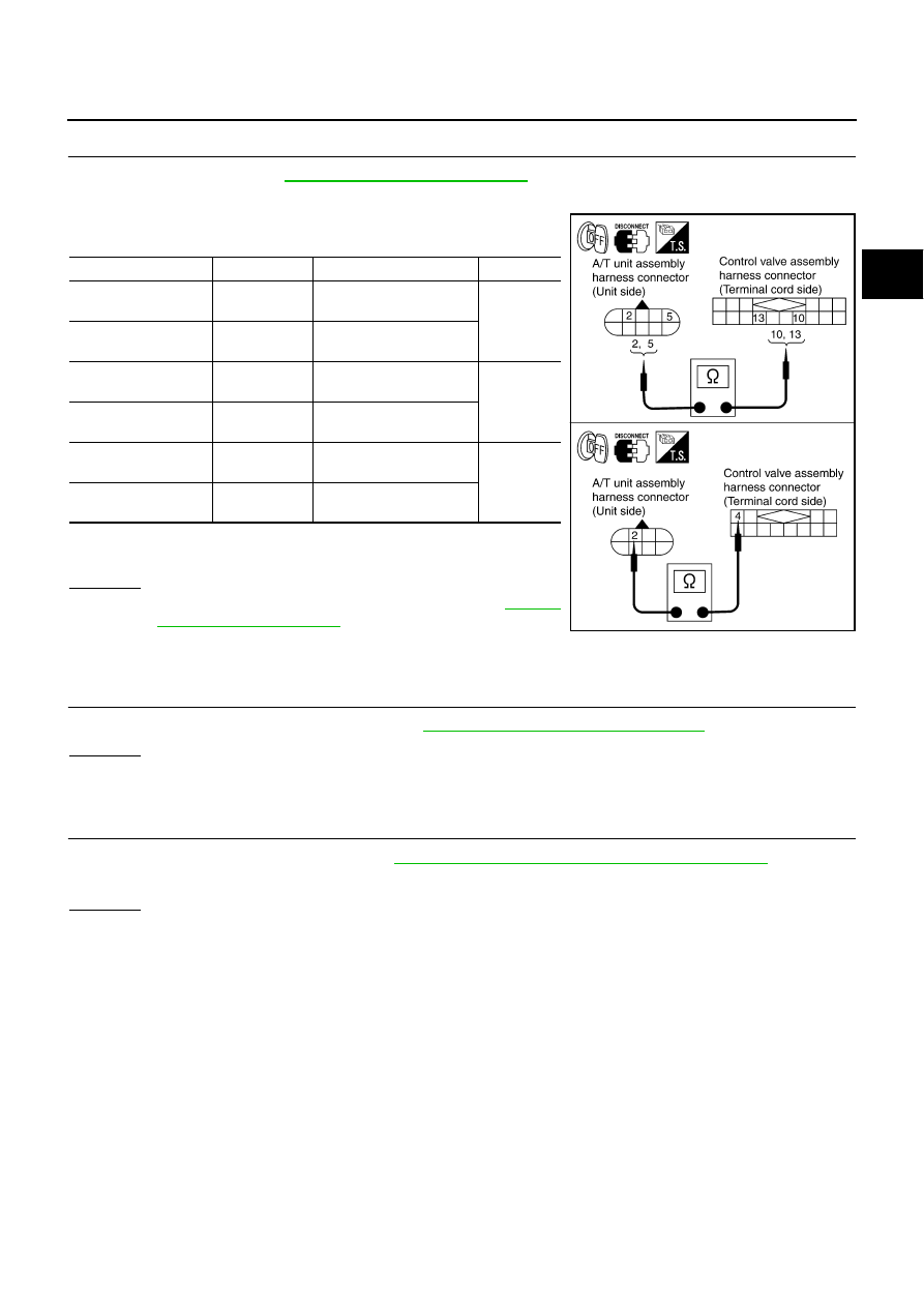
Disconnect A/T unit assembly harness connector and control valve assembly harness connector.

3.

Check continuity between A/T unit assembly harness connector
and control valve assembly harness connector.

4.

If OK, check harness for short to ground and short to power.

5.

Reinstall any part removed.

OK or NG

OK

>> Replace the control valve assembly. Refer to 

AT-312,

"Control Valve Assembly"

 .

NG

>> Repair open circuit or short to ground or short to power

in harness or connectors.

4. 

CHECK DTC

Perform “DTC Confirmation Procedure”. Refer to 

AT-226, "DTC Confirmation Procedure"

 .

OK or NG

OK

>> INSPECTION END

NG

>> GO TO 5.

5. 

CHECK TCM

1.

Check TCM input/output signal. Refer to 

AT-86, "TCM Input/Output Signal Reference Values"

 .

2.

If NG, recheck TCM pin terminals for damage or loose connection with harness connector.

OK or NG

OK

>> INSPECTION END

NG

>> Repair or replace damaged parts.

Item

Connector No.

Terminal No. (Wire color)

Continuity

A/T unit assembly 
harness connector

F26

2 (R)

Yes

Control valve assem-
bly harness connector

F302

10 (R)

A/T unit assembly 
harness connector

F26

5 (L)

Yes

Control valve assem-
bly harness connector

F302

13 (L)

A/T unit assembly 
harness connector

F27

2 (B/R)

Yes

Control valve assem-
bly harness connector

F301

4 (B/R)

SCIA3096E

AT-230

DTC P1815 MANUAL MODE SWITCH

DTC P1815 MANUAL MODE SWITCH

PFP:34901

Description

ACS004AJ

Manual mode switch is installed in A/T device. It sends manual mode switch, shift up and shift down switch
signals to TCM.
TCM sends the switch signals to unified meter and A/C amp by CAN communication line. Then manual mode
switch position is indicated on the A/T position indicator. For inspection, refer to 

AT-233, "A/T Position Indica-

tor"

 .

CONSULT-II Reference Value in Data Monitor Mode

ACS004AK

On Board Diagnosis Logic

ACS004AL

This is not an OBD-II self-diagnostic item. 

Diagnostic trouble code “MANU MODE SW/CIR” with CONSULT-II is detected when TCM monitors Man-
ual mode, Non manual mode, Up or Down switch signal, and detects as irregular when impossible input
pattern occurs 1 second or more.

Possible Cause

ACS004AM

Harness or connectors
(These switches circuit is open or shorted.)

Mode select switch (Into control device)

Position select switch (Into control device)

DTC Confirmation Procedure

ACS004AN

NOTE:
If “DTC Confirmation Procedure” has been previously conducted, always turn ignition switch OFF and
wait at least 10 seconds before conducting the next test.
After the repair, perform the following procedure to confirm the malfunction is eliminated.

 WITH CONSULT-II

1.

Turn ignition switch ON. (Do not start engine.)

2.

Select “DATA MONITOR” mode for “A/T” with CONSULT-II.

3.

Start engine.

4.

Move selector lever to “M” position for at least 2 consecutive
seconds.

5.

If DTC is detected, go to 

AT-232, "Diagnostic Procedure"

 .

Item name

Condition

Display value

MANU MODE SW

Manual shift gate position (neutral)

ON

Other than the above

OFF

NON M-MODE SW

Manual shift gate position

OFF

Other than the above

ON

UP SW LEVER

Select lever: + side

ON

Other than the above

OFF

DOWN SW LEVER

Select lever: - side

ON

Other than the above

OFF

SAT014K

DTC P1815 MANUAL MODE SWITCH

AT-231

D

E

F

G

H

I

J

K

L

M

A

B

AT

Wiring Diagram — AT — MMSW

ACS004AO

TCWA0242E

AT-232

DTC P1815 MANUAL MODE SWITCH

Diagnostic Procedure

ACS004AP

1. 

CHECK MANUAL MODE SWITCH CIRCUIT

 With CONSULT-II

1.

Turn ignition switch ON. (Do not start engine.)

2.

Select “ECU INPUT SIGNALS” in “DATA MONITOR” mode for
“A/T” with CONSULT-II.

3.

Read out ON/OFF switching action of the “MANU MODE SW”,
“NON M-MODE SW”, “UP SW LEVER”, “DOWN SW LEVER”.

 Without CONSULT-II

Drive vehicle in the manual mode, and confirm that the actual gear position and the meter's indication of
the position mutually coincide when the selector lever is shifted to the “+ (up)” or “- (down)” side (1st 

 5th

gear).

OK or NG

OK

>> GO TO 3.

NG

>> GO TO 2.

2. 

DETECT MALFUNCTIONING ITEM

Check the following items.

Power supply. Refer to 

DI-6, "COMBINATION METERS"

 .

Manual mode switch. Refer to 

AT-233, "Component Inspection"

 .

Pin terminals for damage or loose connection with harness connector.

Open circuit or short to ground or short to power in harness or connector for A/T device (manual mode
switch).

OK or NG

OK

>> GO TO 3

NG

>> Repair or replace damaged parts.

3. 

CHECK DTC

Perform DTC confirmation procedure. Refer to 

AT-230, "DTC Confirmation Procedure"

 .

OK or NG

OK

>> INSPECTION END

NG

>> Replace the control device assembly.

Item name

Condition

Display value

MANU MODE SW

Manual shift gate posi-
tion (neutral)

ON

Other than the above

OFF

NON M-MODE SW

Manual shift gate position

OFF

Other than the above

ON

UP SW LEVER

Select lever: + side

ON

Other than the above

OFF

DOWN SW LEVER

Select lever: - side

ON

Other than the above

OFF

PCIA0064E


Content   ..  84  85  86  87   ..