Infiniti M45 (Y34). Manual - part 84
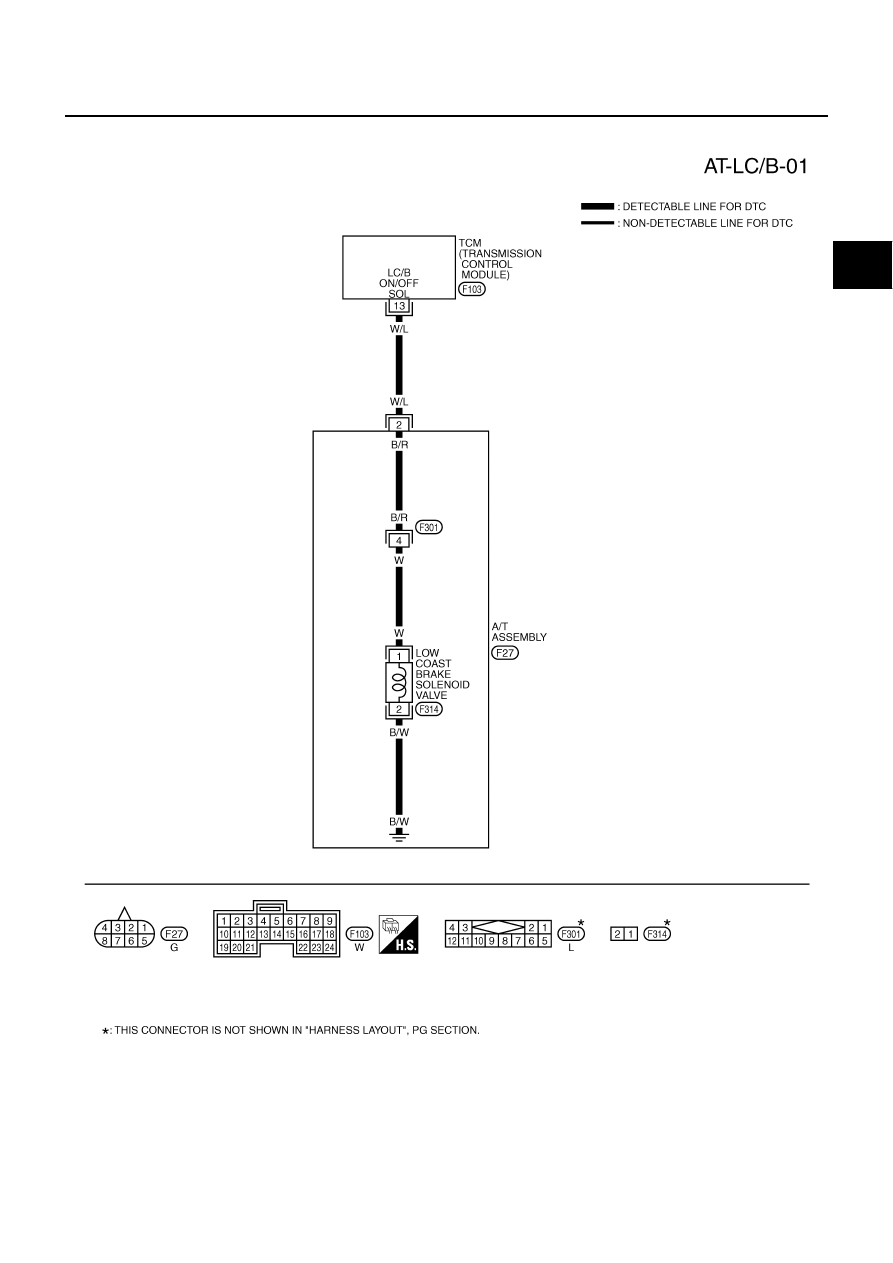
DTC P1772 LOW COAST BRAKE SOLENOID VALVE
AT-221
D
E
F
G
H
I
J
K
L
M
A
B
AT
Wiring Diagram — AT — LC/B
ACS004AA
TCWA0133E
|
|
|
DTC P1772 LOW COAST BRAKE SOLENOID VALVE AT-221 D E F G H I J K L M A B AT Wiring Diagram — AT — LC/B ACS004AA TCWA0133E |