Infiniti M45 (Y34). Manual - part 74
DTC P1752 INPUT CLUTCH SOLENOID VALVE
AT-181
D
E
F
G
H
I
J
K
L
M
A
B
AT
TCM terminal and data are reference value. Measured between each terminal and ground.
Diagnostic Procedure
ACS0048V
1.
CHECK INPUT SIGNALS
With CONSULT-II
1.
Start engine.
2.
Select “MAIN SIGNALS” in “DATA MONITOR” mode for “A/T” with CONSULT-II.
3.
Read out the value of “I/C SOLENOID” while driving.
Without CONSULT-II
1.
Start engine.
2.
Check voltage between TCM connector and ground.
OK or NG
OK >> GO
TO
6.
NG
>> GO TO 2.
Terminal
No.
Wire
color
Item
Condition
Data (Approx.)
10
R/W
Input clutch sole-
noid valve
When
vehicle
cruises
When the solenoid valve operating (in 1st gear, 2nd gear,
or 3rd gear)
More than 2.0V
When the solenoid valve is not operating (4th gear or 5th
gear)
0V
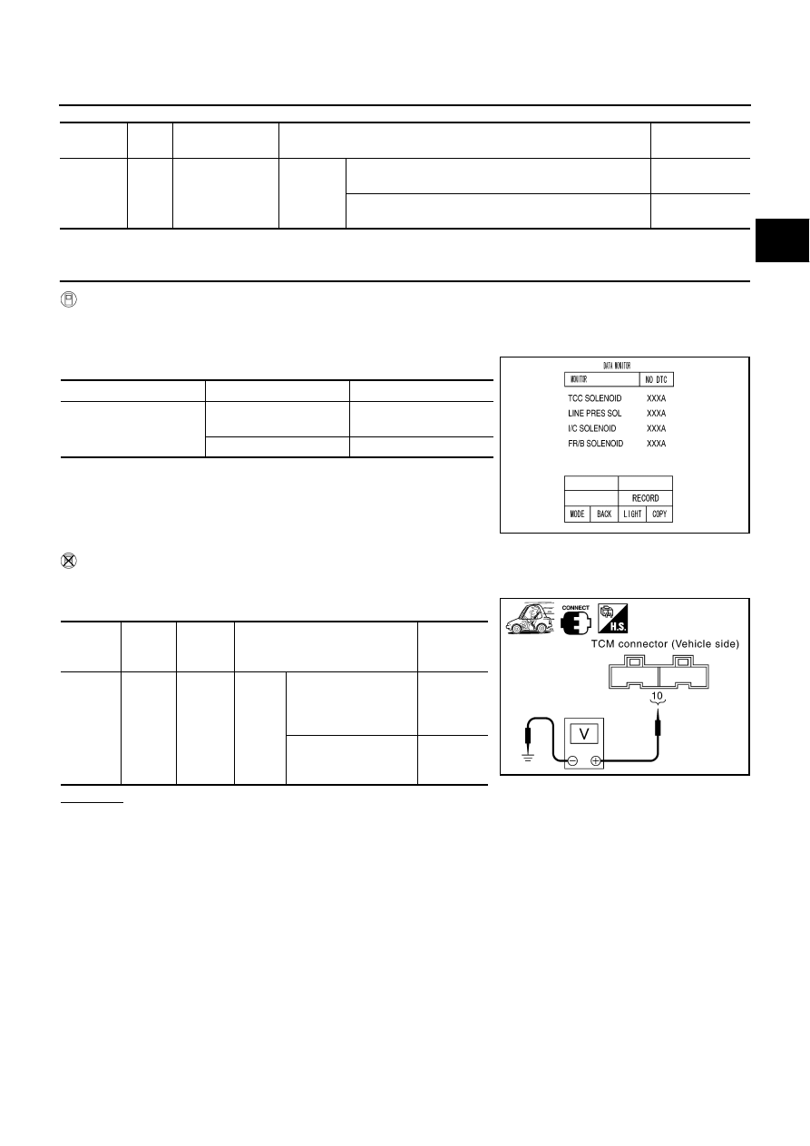
Item name
Condition
Display value (Approx.)
I/C SOLENOID
Input clutch solenoid
valve operates.
0.6 - 0.8 A
Other conditions
0 - 0.05 A
SCIA4462E
Item
Con-
nector
No.
Terminal
No.
Condition
Data
(Approx.)
Input
clutch
solenoid
valve
F103
10 (R/
W) -
Ground
When
vehicle
cruises
When the solenoid
valve operating (in 1st
gear, 2nd gear, or 3rd
gear)
More than
2V
When the solenoid
valve is not operating
(4th gear or 5th gear)
0V
SCIA4573E