Index Infiniti Infiniti M45 (Y34) - service repair manual 2004 year
Search copyright infringement
Content .. 69 70 71 72 ..
Infiniti M45 (Y34). Manual - part 71
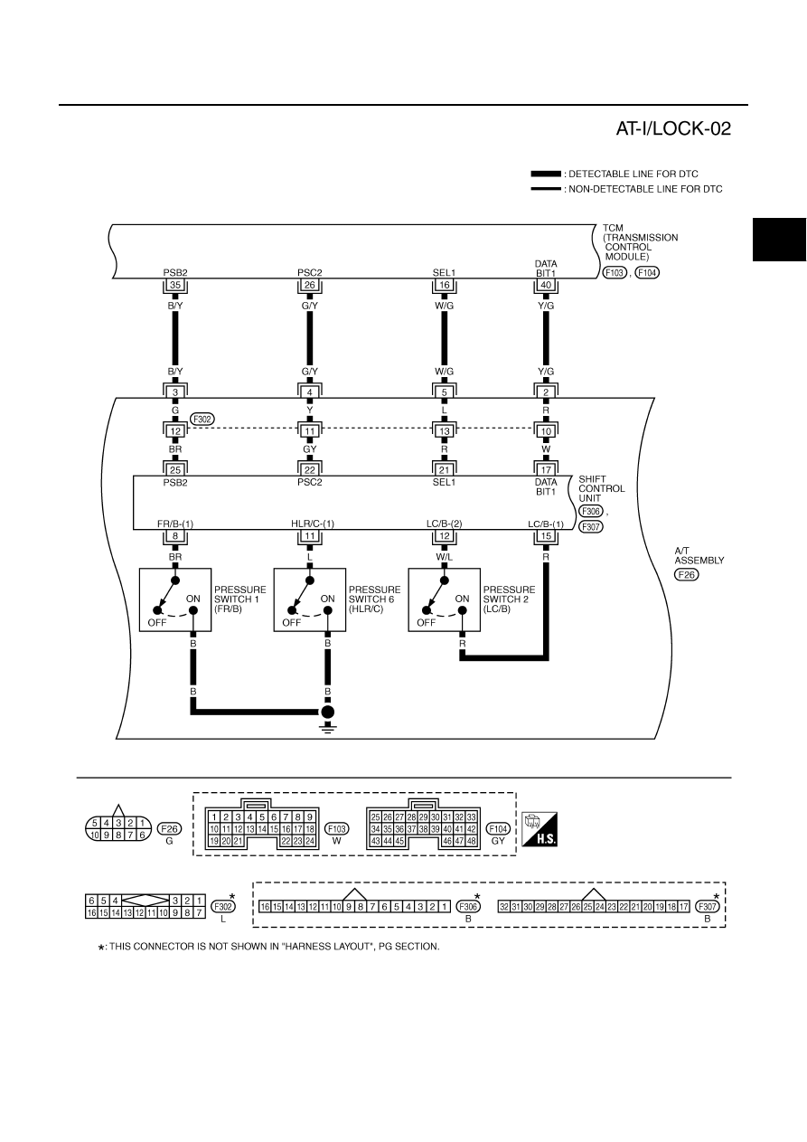
DTC P1730 A/T INTERLOCK
AT-169
D
E
F
G
H
I
J
K
L
M
A
B
AT
TCWA0122E