Infiniti M45 (Y34). Manual - part 60
DTC P0740 TORQUE CONVERTER CLUTCH SOLENOID VALVE
AT-125
D
E
F
G
H
I
J
K
L
M
A
B
AT
TCM terminal and data are reference value. Measured between each terminal and ground.
Diagnostic Procedure
ACS0047Q
1.
CHECK INPUT SIGNALS
With CONSULT-II
1.
Start engine.
2.
Select “MAIN SIGNALS” in “DATA MONITOR” mode for “A/T” with CONSULT-II.
3.
Read out the value of “TCC SOLENOID” while driving.
Check the value changes according to driving speed.
Without CONSULT-II
1.
Start engine.
2.
Check voltage between TCM connector and ground.
OK or NG
OK >> GO
TO
6.
NG
>> GO TO 2.
2.
CHECK TORQUE CONVERTER CLUTCH SOLENOID VALVE CIRCUIT
1.
Turn ignition switch OFF.
2.
Disconnect A/T unit assembly harness connector at the trans-
mission right side.
3.
Check the resistance between terminal and ground.
OK or NG
OK >> GO
TO
5.
NG
>> GO TO 3.
Terminal
No.
Wire
color
Item
Condition
Data (Approx.)
20
Y
TCC solenoid
valve
When
vehicle
cruises
When lock-up
More than 2V
When not lock-up
0V
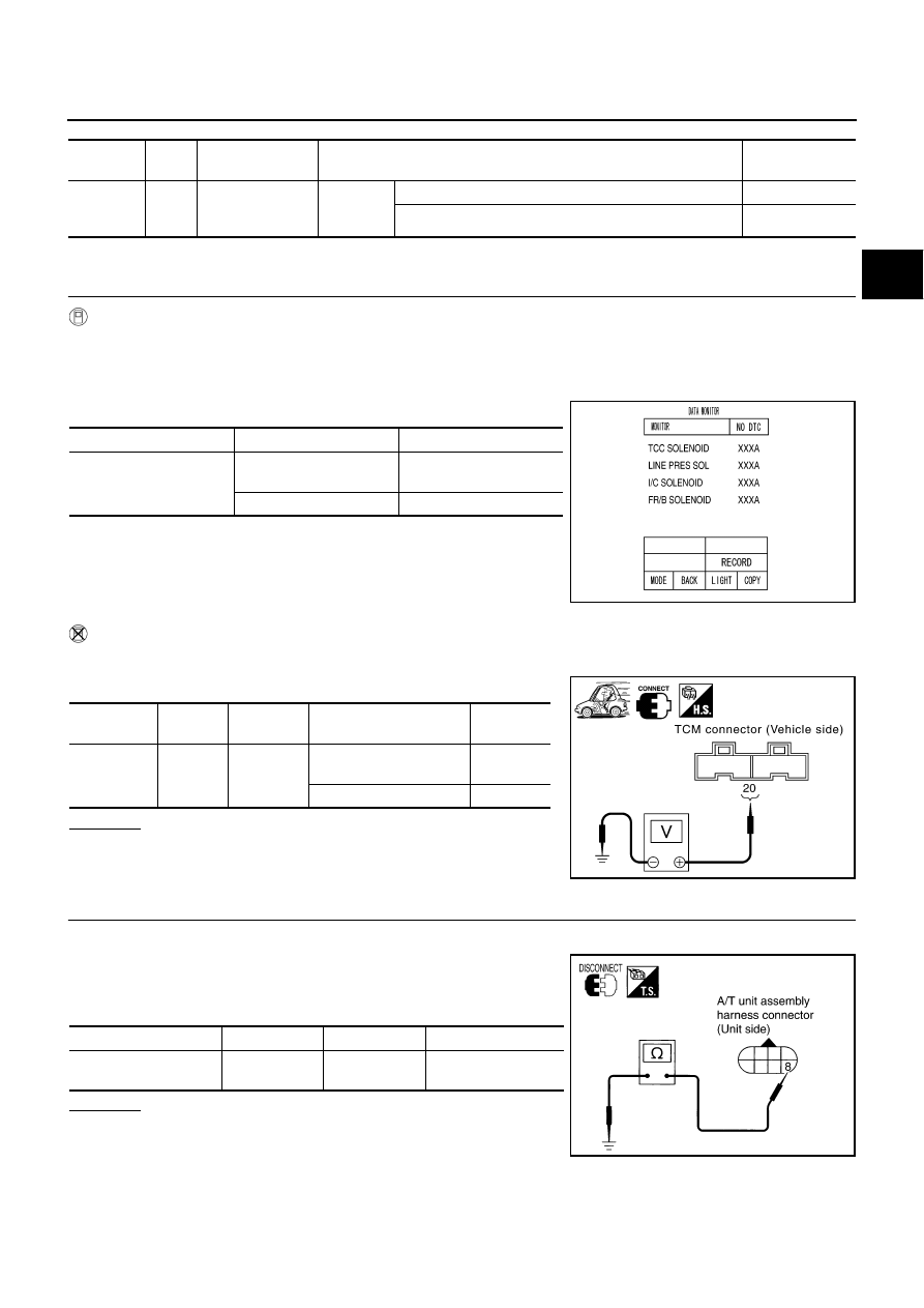
Item name
Condition
Display value (Approx.)
TCC SOLENOID
When perform slip lock-
up
0.2 - 0.4A
When perform lock-up
0.4 - 0.6A
SCIA4462E
Item
Connec-
tor No.
Terminal
No.
Condition
Data
(Approx.)
TCC sole-
noid valve
F103
20 (Y) -
Ground
When lock-up
More than
2V
When not lock-up
0V
SCIA4464E
Solenoid valve
Connector No.
Terminal No.
Resistance (Approx.)
Torque converter clutch
solenoid valve
F27
8 - Ground
3 - 9
Ω
SCIA1830E