Infiniti M45 (Y34). Manual - part 5
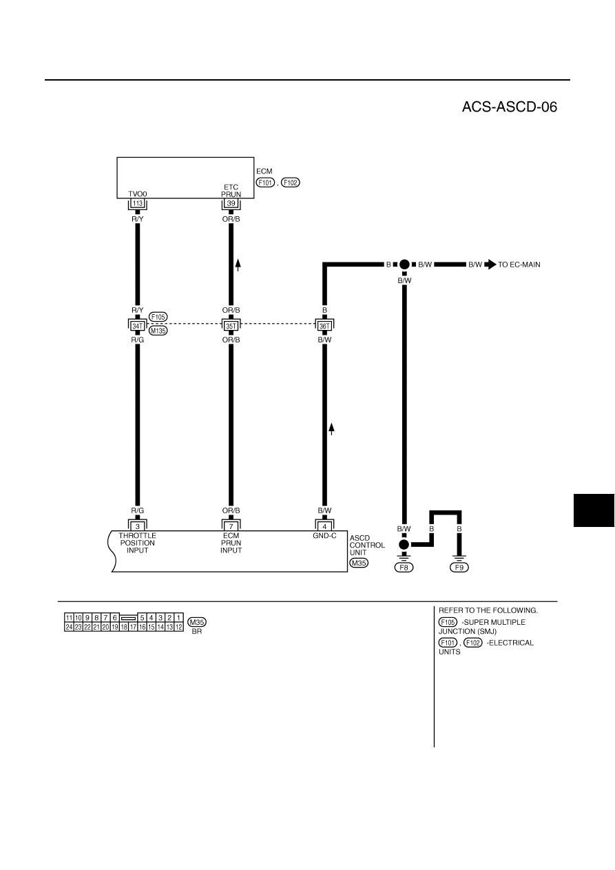
AUTOMATIC SPEED CONTROL DEVICE (ASCD)
ACS-13
[ASCD]
C
D
E
F
G
H
I
J
L
M
A
B
ACS
FIG. 6
TKWA0673E
|
|
|
AUTOMATIC SPEED CONTROL DEVICE (ASCD) ACS-13 [ASCD] C D E F G H I J L M A B ACS FIG. 6 TKWA0673E |