Content .. 997 998 999 1000 ..
Infiniti M35/M45 Y50. Manual - part 999
STEERING WHEEL
PS-11
C
D
E
F
H
I
J
K
L
M
A
B
PS
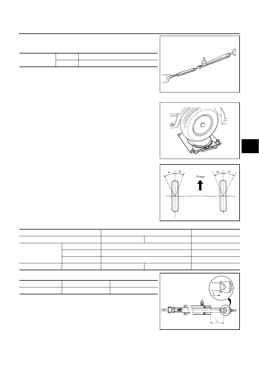
c.
While pulling outer socket slowly in
±
11.5 mm (
±
0.453 in) range
from neutral position, make sure rack sliding force is within
specification.
d.
If rack sliding force is not within specification, overhaul steering
gear assembly.
CHECKING FRONT WHEEL TURNING ANGLE
●
Check front wheel turning angle after toe-in inspection. Place
front wheels on turning radius gauges and rear wheels on
stands. Check the maximum inner and outer wheel turning
angles for LH and RH road wheels.
●
With the engine at idle, turn steering wheel from full left stop to
full right stop and measure the turning angles.
●
Measure rack stroke if angles are outside the specified value.
●
Disassemble steering gear assembly to check the cause that
rack stroke is outside of the standard.
●
Steering angles are not adjustable. Check steering gear assem-
bly, steering column assembly and front suspension compo-
nents for wear or damage if any of the turning angles are
different from the specified value. Replace any of them, if any
non-standard condition exists.
Rack sliding force
2WD
195 – 258 N (19.9 – 26.3 kg, 44 – 58 lb)
AWD
227 – 305 N (23.2 – 31.1 kg, 51 – 69 lb)
SST090B
FAA0016D
SGIA0055E
Drive type
2WD
AWD
Tire size
245/45R18
245/40R19
245/45R18
Inner wheel (Angle: A)
Minimum
36
°
20
′
(36.3
°
)
39
°
45
′
(39.8
°
)
Nominal
39
°
20
′
(39.3
°
)
42
°
45
′
(42.8
°
)
Maximum
40
°
20
′
(40.3
°
)
43
°
45
′
(43.8
°
)
Outer wheel (Angle: B)
Nominal
33
°
25
′
(33.4
°
)
33
°
20
′
(33.3
°
)
32
°
30
′
(32.5
°
)
Drive type
2WD
AWD
Rack stroke L
68.5 mm (2.697 in)
67.0 mm (2.638 in)
SGIA0629J